Overfire air port and furnace system

a furnace system and air port technology, applied in the field of furnace systems, can solve the problems of reducing affecting the efficiency of air ports, so as to and reduce the amount of ubc and co

Inactive Publication Date: 2006-05-23
FOSTER WHEELER NORTH AMERICA CORP
View PDF14 Cites 16 Cited by
  • Summary
  • Abstract
  • Description
  • Claims
  • Application Information

AI Technical Summary

Benefits of technology

[0013]In addition to substantially reducing NOx output, the design of the furnace of the present invention has also been developed to reduce the amount of CO emitted from the furnace. By removing a portion of the combustion air from the combustion zone and injecting such air through OFA ports arranged in the lanes above the combustion zone and between the outermost ends thereof and the furnace wall, oxygen in the OFA will be injected into the furnace to oxidize CO traveling up the lanes and to thus convert such CO into CO2. Moreover, placement of the OFA ports in the lanes between the burners at the edges of the combustion zone and furnace walls allow for greater mixing of the OFA with CO, which flows upward in the lane to maximize conversion of CO into CO2 before a substantial portion of the CO exits the furnace. Accordingly, the configuration of the OFA ports reduces the amount of CO present in the furnace and subsequently released into the atmosphere.
[0034]It is still another object of the present invention to provide an OFA port which overcomes the problems of unsymmetrical mixing about the OFA port vertical centerline, which in turn permits unmixed furnace gases, which yield non-minimum amounts of CO and other products of incomplete combustion, to flow unchanged to the furnace exit.

Problems solved by technology

In the absence of such excess air, significant quantities of by-products are produced due to incomplete combustion.
Such conditions result in a significant reduction and prevention of the formation of NOx, but simultaneously cause the formation of high levels of carbon monoxide (CO) and unburned carbon products (UBC).
Prior art two stage OFA ports are subject to various problems.
One of the defects of the swirling outer flow is that rotational flow results in up-flow along one side of the port and down-flow on the other side.
Because the mixing is not symmetrical about the vertical centerline of the port, unmixed furnace gases are permitted to pass by the port yielding undesirable amounts of CO and other by-products of incomplete combustion, which flow out of the furnace.

Method used


Image

  • Overfire air port and furnace system
  • Overfire air port and furnace system
  • Overfire air port and furnace system

Examples


Embodiment Construction

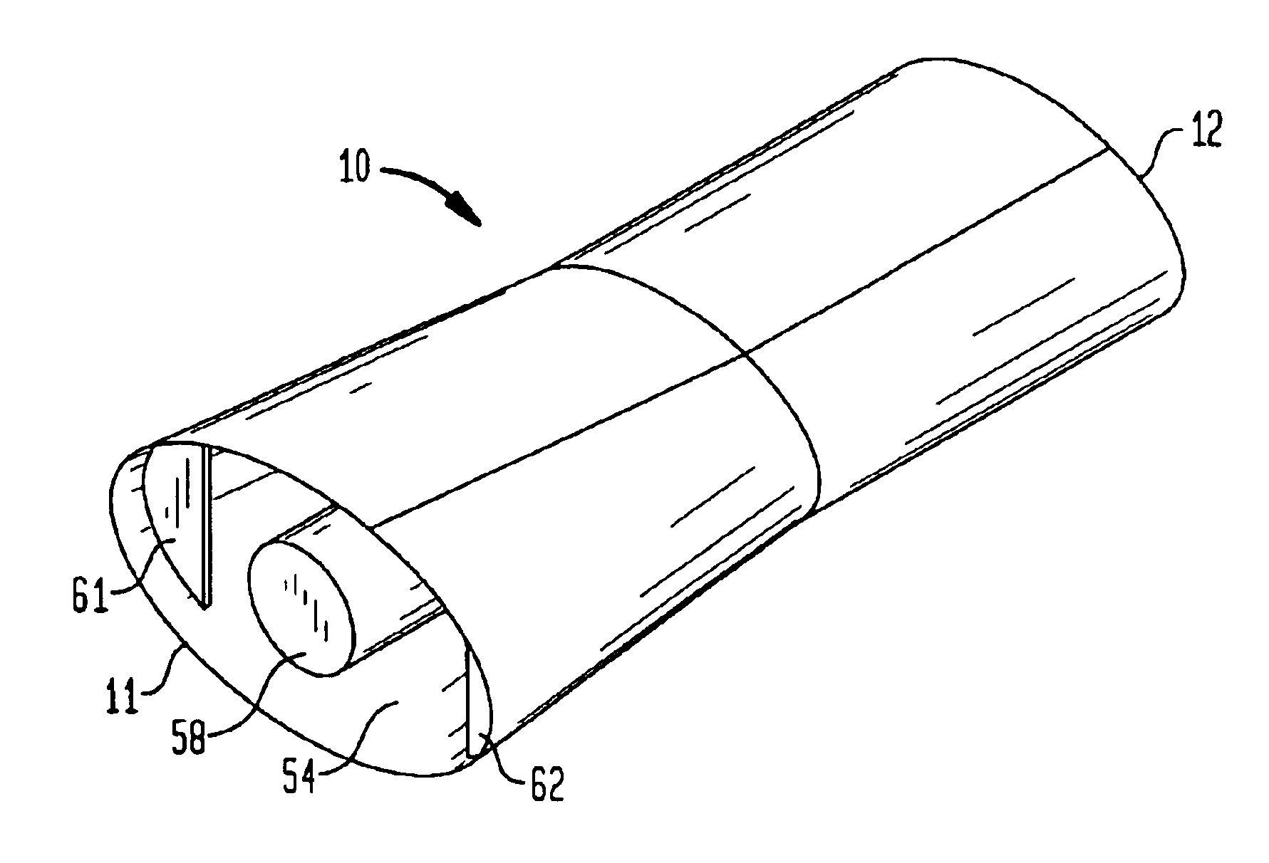
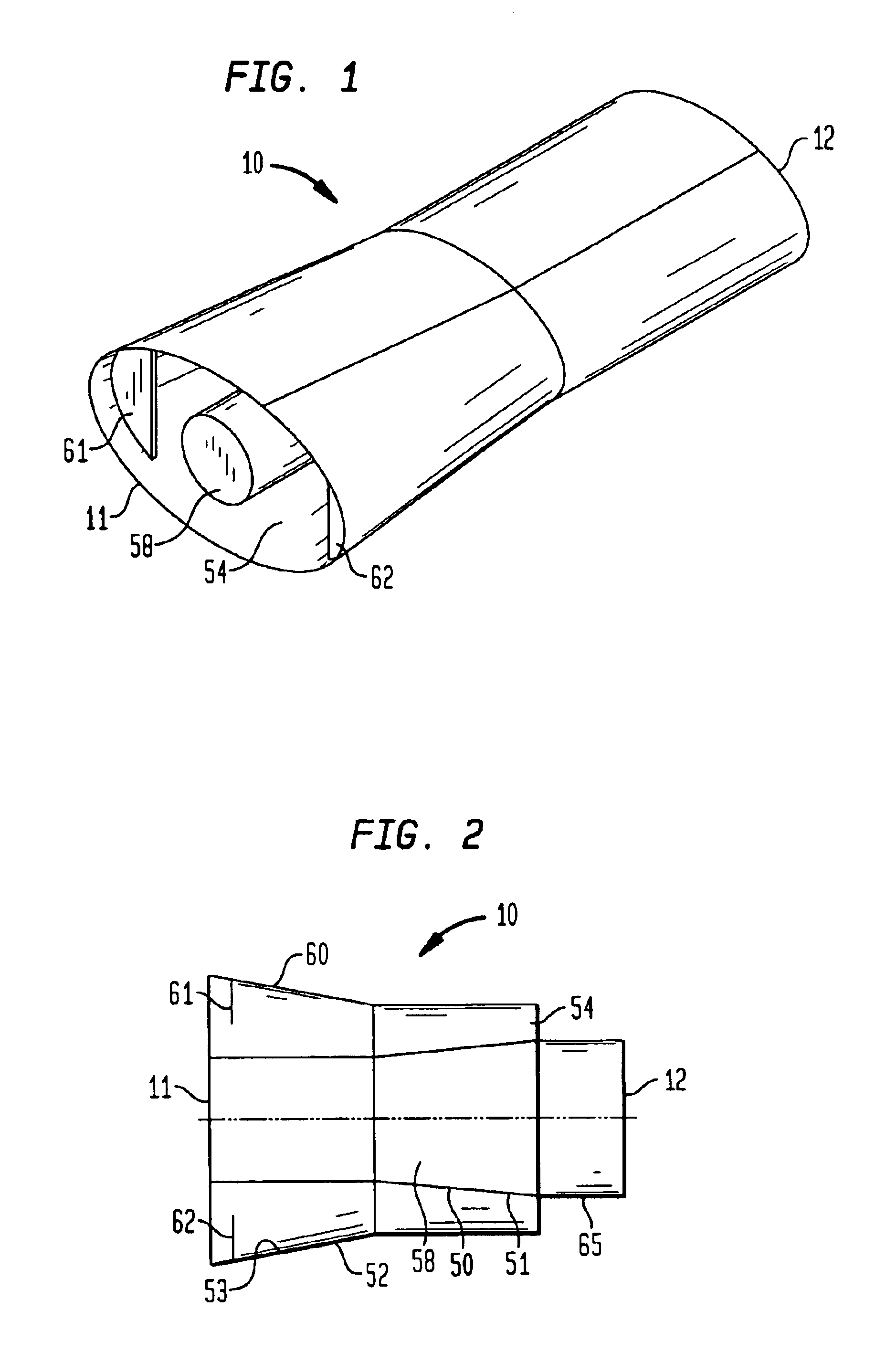
[0046]As shown in FIGS. 1 and 2 an overfire air (OFA) port 10 of the present invention includes an outlet end 11 and an inlet end 12. In the preferred embodiment of FIG. 1, the OFA port 10 is generally tapered from a relatively large elliptical diameter at the outlet end 11 to a relatively circular diameter at the inlet end 12. The materials of which the OFA port may be made are conventional and may include various materials capable of withstanding extreme heat, such as iron, steel, ceramic or the like.

[0047]As shown in FIG. 2, the OFA port 10 includes an elongated inner barrel 50 defining an inner passageway 58 and an elongated outer barrel 52 that surrounds inner barrel 50 and extends substantially coaxially therewith.

[0048]An outer passageway 54 is formed between the inner barrel 50 and the outer barrel 52. Both the inner passageway 58 and outer passageway 54 are generally annular and are used as flow paths for reinjecting OFA into and associated the furnace.

[0049]As shown in FIG...


PUM


Abstract

An Overfire Air (OFA) port design and method for use in a furnace system is disclosed. The OFA port design effectively reduces the amount of harmful pollutants emitted into the atmosphere upon discharge from an associated furnace.

Description

CROSS-REFERENCE TO RELATED APPLICATION[0001]This application claims benefit of U.S. Provisional Patent Application 60 / 355,674, filed Feb. 7, 2002, the disclosure of which is incorporated by reference herein.BACKGROUND OF THE INVENTION[0002]This invention relates to furnace systems and more particularly to furnace systems, which employ an overfire air (OFA) process to reduce harmful by-products, such as CO, NOx and unburned carbon products.[0003]The complete combustion of fossil fuels or other types of organic and chemical fuels in a furnace requires a fixed and known quantity of combustion air. The relationship between air and fuel is known as stoichiometric combustion conditions. Because the supply of stoichiometric air to the combustion and subsequent consumption of fuel is theoretical, a furnace of infinite size would be required to achieve complete combustion. In existing furnaces, more air is supplied than is theoretically required. This additional quantity is referred to as ex...

Claims


Application Information

Patent Timeline
Patent Type & Authority Patents(United States)
IPC IPC(8): F23L13/00F23L9/02F23C99/00F23L9/04F27D7/02
CPCF23L9/04F23M9/02F27D7/00
Inventor VATSKY, JOEL
Owner FOSTER WHEELER NORTH AMERICA CORP
Why Eureka
Try Eureka