
Link plate for a silent chain

Inactive Publication Date: 2006-05-23
BORG WARNER MORSE TEC JAPAN KK
View PDF8 Cites 6 Cited by
  • Summary
  • Abstract
  • Description
  • Claims
  • Application Information

AI Technical Summary

Benefits of technology

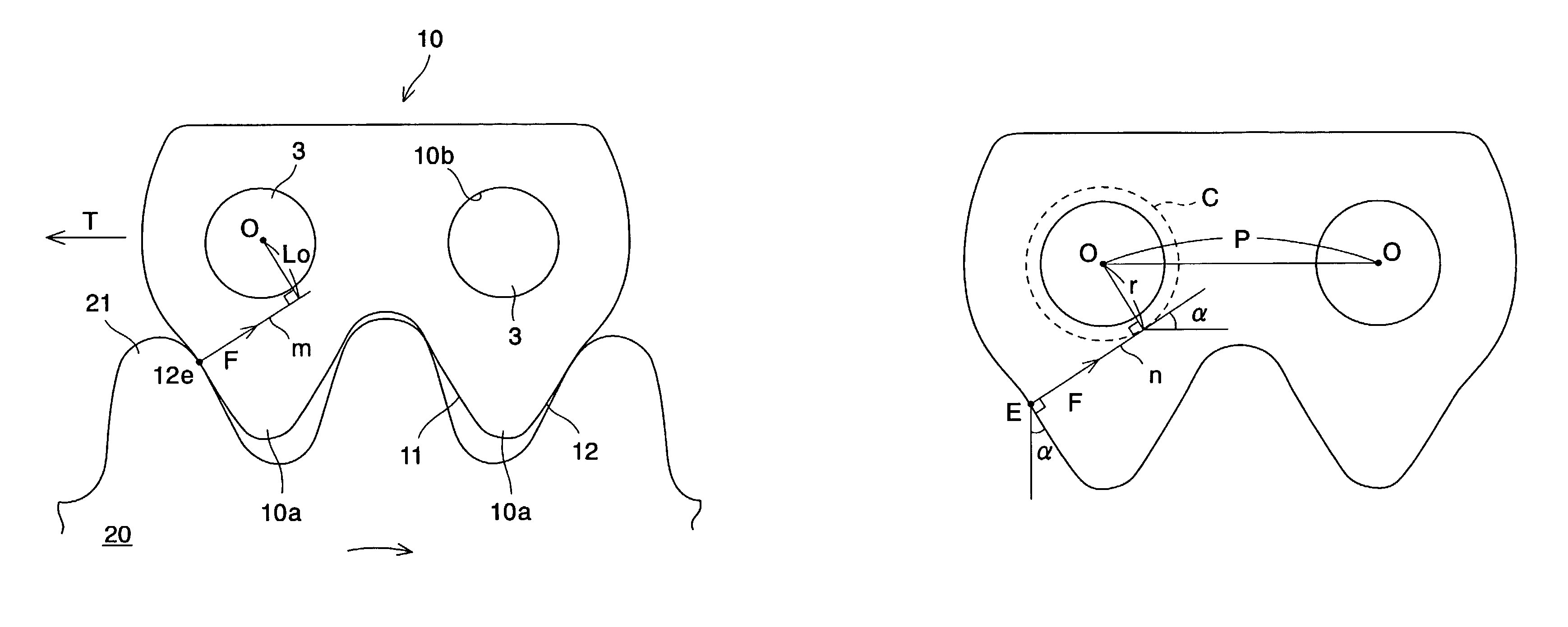
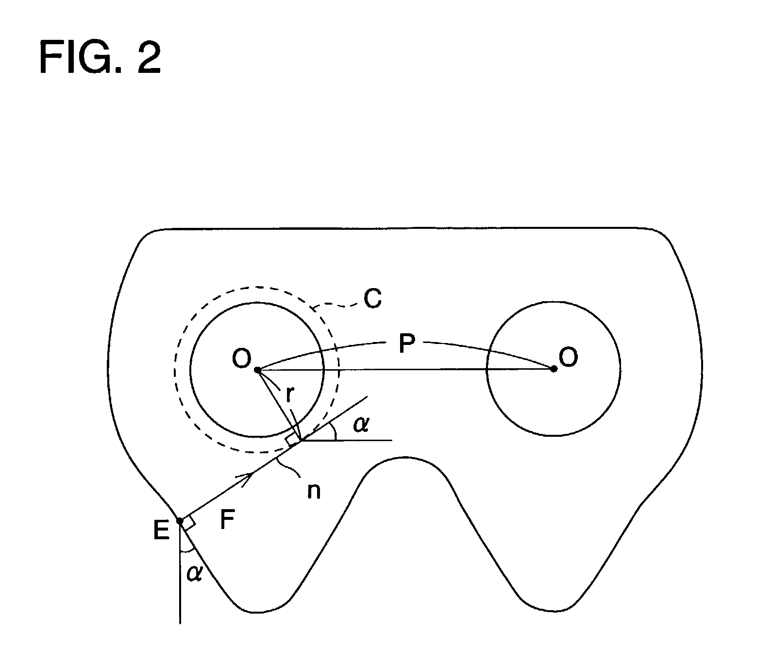
[0009]As is seen from FIG. 2, the straight line n corresponds to an action line of force F applied from the sprocket tooth to the engaging point E of the link plate. The radius r of the circle C corresponds to a length of a perpendicular drawn from the center O of the pin aperture to the action line of the force F at the engaging point E. Also, the radius r satisfies an inequality, r≦0.25×P (as opposed to a prior art link plate, in which there was an inequality, r>0.25×P), and the radius r is small. Thus, around-the-pin moment M (=F×r) is relatively small, thereby decreasing primary oscillation of engagement. Moreover, in the present invention, an arm length of around-the-pin moment can be shortened irrespective of the size of the pressure angle α of the flank. Preferably, the pressure angle α of the flank satisfies an inequality, α>30°.
[0010]The connecting pin may be a round, cylindrical pin of a round sectional shape. Alternatively, the connecting pin may be a rocker joint formed of a rocker pin and a joint pin. In a rocker joint type silent chain, an intersecting point O′ (not shown) between a rocker pin and a joint pin with the silent chain linearly extended corresponds to a center O of the pin aperture for a round pin. In the case of a rocker joint type silent chain as well, the arm length of around-the-pin moment can be shortened regardless of the size of the pressure angle α of the flank. Thus, around-the-pin moment can be made relatively small, thereby decreasing primary oscillation sound of engagement.
[0011]Therefore, from a viewpoint of lessening the around-the-pin moment and preventing tooth jumping of a sprocket tooth, the pressure angle α, more preferably, satisfies an inequality, 32°≦α<34°. In this case, not only an arm length of the moment but also a component of a force constituting the moment can be lessened, thereby further decreasing around-the-pin moment, thus further reducing primary oscillation sound.

Problems solved by technology

There are various frequencies in noise that occurs during operation of a silent chain.

Method used


Image

  • Link plate for a silent chain
  • Link plate for a silent chain
  • Link plate for a silent chain

Examples


Embodiment Construction

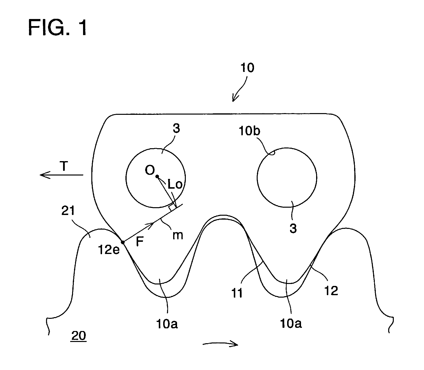
[0023]Moment of a force around a connecting pin (hereinafter called “around-the-pin moment”) that is applied to an engagement surface of a link plate at the time of meshing with a sprocket tooth greatly influences the primary oscillation of engagement. According to the teachings of this invention, when around-the-pin moment M becomes greater, fluctuation in tension easily occurs, and such torque fluctuation occurs synchronized with engaging frequency, thereby causing primary oscillation of engagement, which transmits to a peripheral device and becomes a source of engaging sound. Therefore, primary oscillation sound will be decreased by decreasing around-the-pin moment.

[0024]Referring now to the drawings, FIG. 1 shows a portion of a silent chain having a plurality of rows of link plates provided along the length of the chain, illustrating a link plate of a specified row engaging with a sprocket. As shown in FIG. 1, a link plate 10 includes a pair of teeth 10a and pin apertures 10b. E...


PUM


Abstract

A link plate for silent chains includes a pair of teeth, each formed of an inside flank and an outside flank and a pair of pin apertures. A moment of force around a pin M=F×Lo, where F is a force applied by a sprocket tooth against the outside flank, and Lo is a length of a perpendicular drawn from a center O of a pin aperture to an action line of the force, is decreased by decreasing Lo. The link plate engages a sprocket tooth on an intersection between a straight line n and a flank, line n and the direction of a central line connecting each O forming a pressure angle α, and contacting a circle having a center O and a radius r<0.25×P, where P is a pin aperture pitch. Also, α of the outside flank satisfies an inequality, 32°≦α<34°, to lessen the force.

Description

BACKGROUND OF THE INVENTION[0001]1. Field of the Invention[0002]The present invention relates to a link plate for a silent chain, and more particularly, to an improvement of structure to decrease noise of the silent chain during operation.[0003]2. Description of Related Art[0004]A silent chain is generally constructed from a plurality of link plates each having a pair of teeth and pin apertures and arranged in lateral and longitudinal directions and joined pivotably by connecting pins.[0005]There are various frequencies in noise that occurs during operation of a silent chain. In these frequencies, a frequency having the greatest intensity forms a so-called primary oscillation of engagement. Since such primary oscillation of engagement gives objectionable impression to ears of human beings, various efforts and improvements have been made to decrease the primary oscillation of engagement.[0006]Referring to FIG. 6, the around-the-pin moment will be explained. FIG. 6 shows a state of en...

Claims


Application Information

Patent Timeline
IPC IPC(8): F16G13/04F16G13/06
CPCF16G13/04
Inventor KOTERA, TETSUJI
Owner BORG WARNER MORSE TEC JAPAN KK
Learn More