Method for measuring 3-dimensional orientation of a photoactive moiety

a technology of photoactive moiety and 3-dimensional orientation, which is applied in the direction of fluorescence/phosphorescence, liquid/fluent solid measurement, instruments, etc., can solve the problems of inability to provide information about three-dimensional orientation relationships among objects, limited number of objects which can be tracked simultaneously, and several limitations of the techniqu

Inactive Publication Date: 2006-05-23
MASSACHUSETTS INST OF TECH
View PDF2 Cites 58 Cited by
  • Summary
  • Abstract
  • Description
  • Claims
  • Application Information

AI Technical Summary

Benefits of technology

[0010]In yet another aspect, the method of the invention for providing an identification unit includes selecting an item of interest and providing an identifier wherein the identifier includes at least one particle having characteristic spectral emission. One or more reactive moieties are provided which are attached to the surface of the particle wherein the one or more reactive moieties are selected for their ability to be compatible with the item of interest. The spectral emission of the at least one particle is at least characterized by polarization. In one embodiment, the item of interest is selected from the group consisting of identification tag, security tag, consumer product, fluid, gas, solid, biomolecule, and chemical compound. In another embodiment, the spectral emission of the at least one particle is further characterized by wavelength, intensity, or both.
[0011]In yet another aspect, the invention is a library of items of interest wherein each item of interest has associated with it one or more identifiers wherein the one or more identifiers each comprise a particle with a characteristic spectral emission in which the spectral emission is characterized at least in part by polarization. In one embodiment of this aspect of the invention, the item of interest is selected from the group consisting of identification tag, security tag, consumer product, fluid, gas, solid, biomolecule, and chemical compound. The spectral emission of the at least one particle is further characterized by wavelength intensity or both.

Problems solved by technology

However, this technique has several limitations.
The number of objects which can be tracked simultaneously is limited by the fluorescent wavelengths available from the tags.
In addition, this technique cannot provide information about three dimensional orientation relationships among objects.
However, SNOM is a relatively invasive technique which, in addition, can only analyze one small region of a sample at a time.
Thus, the technique is not useful for high-throughput screening.
Because of the small field of view, only a small total area can be analyzed, resulting in sampling errors.
As a result, if a sample exhibits large amounts of variation, SNOM may not reveal the full variability of the sample.
While far field microscopy can probe larger areas, it can only provide two-dimensional information about the orientation of a molecule with respect to the plane of the sample under observation.

Method used


Image

  • Method for measuring 3-dimensional orientation of a photoactive moiety
  • Method for measuring 3-dimensional orientation of a photoactive moiety
  • Method for measuring 3-dimensional orientation of a photoactive moiety

Examples


example 1

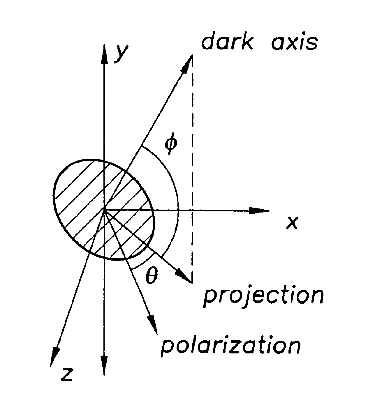
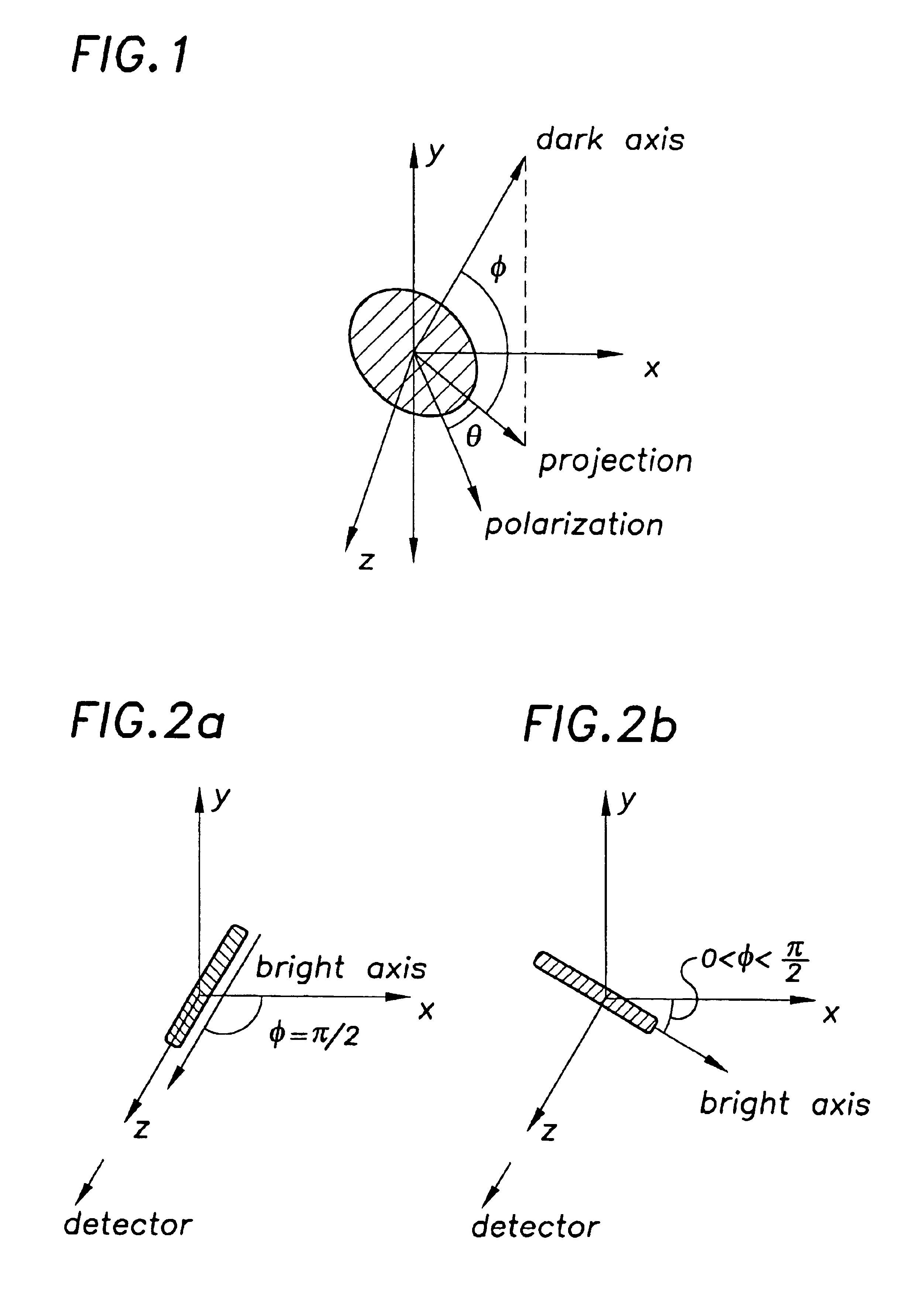
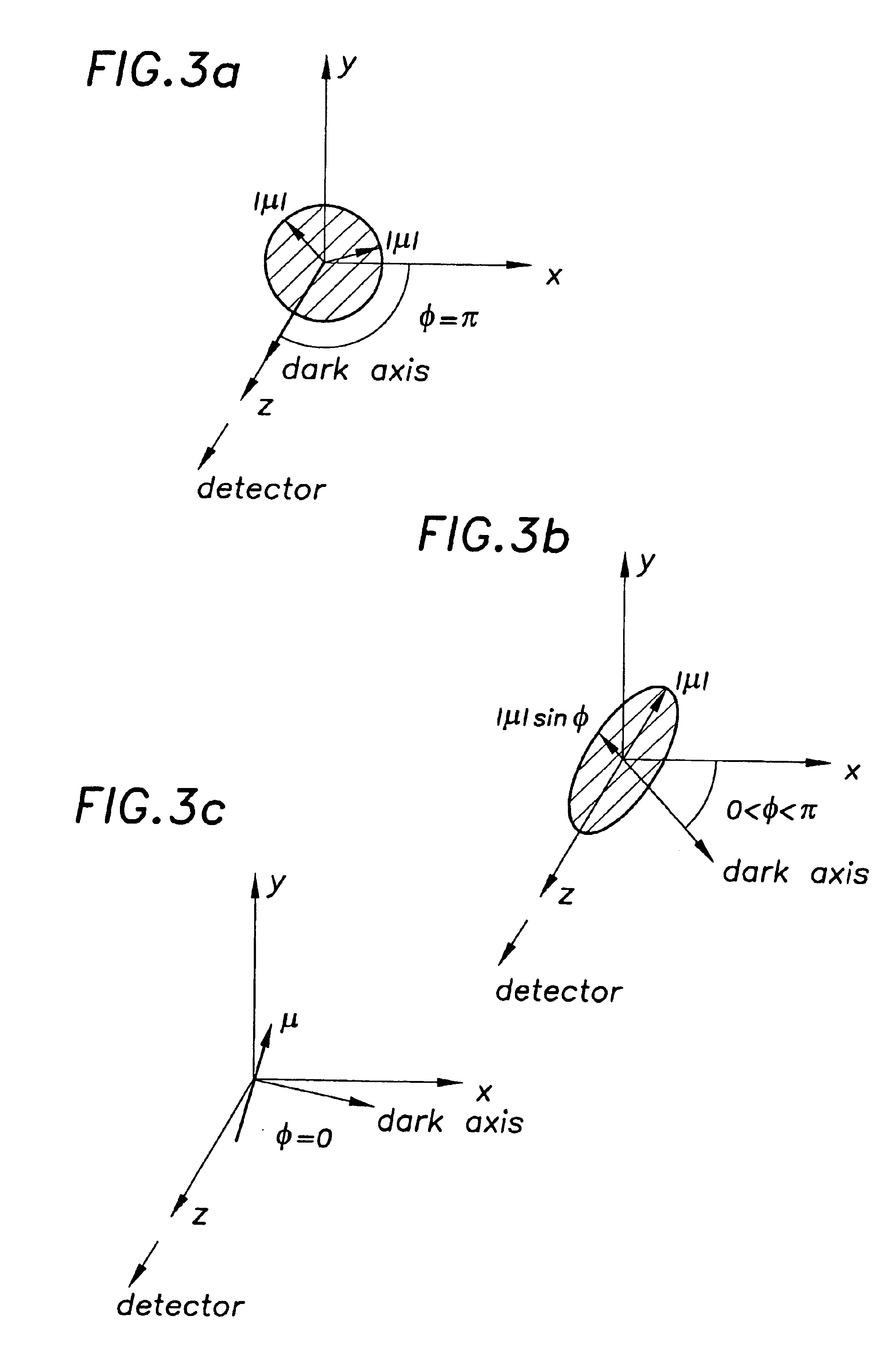
[0027]In general, fluorescent detection can be used to locate and identify objects. The objects are labeled with identifiers composed of one or more markers which fluoresce at different wavelengths or, perhaps, at different intensities. Depending on the number of different wavelengths and intensities and how the different markers are mixed, a given number of different items can be detected. For example, for a given identifier, one may choose from blue, red, green or orange markers, which in turn may exhibit low or high fluorescent intensity. With this invention, one can add an extra variable, the polarization of the fluorescent emission, thereby increasing the number of different objects which can be detected. The markers would then exhibit a bright or dark axis or isotropic emission. For bright or dark axis molecules, the orientation of the axis can also be used as a label. The markers are irradiated, and the resulting emission correlated with the location of the particle. An appro...

example 2

[0029]This invention can be used according to conventional techniques to identify or track the motion of an object. By repeatedly exciting the markers, the motion of a large number of objects can be detected. The operator can then correlate the emission from the marker with the position of the object being tracked. If the markers are phosphorescent, the motion of the objects can be tracked continuously for short periods of time. Orientation information can be gathered directly if the markers are dark axis emitters. If a magnetic moiety is added to the marker, then the magnetic label can be used to set up an initial orientation with respect to an external magnetic field before the object is set in motion. However, the unique properties of the anisotropic emission dipole enables one to track much more than simple motion from point A to point B. As an object moves, it may change its orientation with respect to a fixed reference axis. As this orientation changes, the marker, which is fi...

example 3

[0031]This invention can also be used to track the motion of a gas, liquid, or other fluid. In this case, of course, the identifying marker is not attached to the medium. Instead, markers or even free photoactive molecules are simply released within the fluid. Indeed, it is not even necessary to fix the molecules within a matrix so long as they exhibit a bright axis in their natural state. If the medium is irradiated with polarized light, only molecules having the same orientation as the polarization axis of the absorbed radiation will emit light. If the molecules or markers exhibit a bright axis, then the stimulating radiation should be polarized along only two dimensions. Naturally, markers which have been photobleached to produce either a dark or bright axis can also be used to track the motion of the fluid. The radiation absorbed by the markers or molecules creates a transient emission dipole in the collection of markers. That is, because only some of the emission dipoles are st...


PUM

PropertyMeasurementUnit
wavelengthaaaaaaaaaa
emission wavelengthsaaaaaaaaaa

Abstract

A photoactive moiety exhibiting an anisotropic transition dipole. The moiety exhibits emission of polarized light in response to energy absorption. In a preferred embodiment, the moiety comprises a particle from the group consisting of a crystalline arrangement of photoactive molecules and a photoactive nanocrystal. The moiety may include a matrix in which photoactive objects exhibiting an anisotropic emission dipole are embedded. The moiety may be photobleached to product the anisotropy and the photoactive objects may have a one dimensional transition dipole in their natural state.

Description

[0001]This application is a divisional of and claims the priority of U.S. patent application Ser. No. 09 / 310,009, filed May 11, 1999, now U.S. Pat. No. 6,696,299 the entire contents of which are incorporated by reference herein.[0002]This invention was made with government support under Grant Number DMR-9808941, awarded by NSF. The government has certain rights in the invention.FIELD OF THE INVENTION[0003]This invention relates to the production and use of polarization labels for identifying three dimensional orientation, more specifically, three dimensional orientation of light emitting and absorbing objects.BACKGROUND OF THE INVENTION[0004]Fluorescent labeling is a very powerful technique for locating and tracking tagged objects, with applications in areas ranging from molecular dynamics and combinatorial chemistry to security systems and inventory control. However, this technique has several limitations. The number of objects which can be tracked simultaneously is limited by the ...

Claims


Application Information

Patent Timeline
Patent Type & Authority Patents(United States)
IPC IPC(8): G01N37/00G01F1/704G01N21/64G01N33/58G01P5/00G01P5/20
CPCB82Y15/00G01F1/704G01N21/6445G01P5/001G01P5/20G01N33/588Y10T436/13
Inventor BAWENDI, MOUNGIEMPEDOCLES, STEPHEN
Owner MASSACHUSETTS INST OF TECH
Why Eureka
Try Eureka