Cutting guide for plasma torch

a plasma torch and cutting guide technology, applied in the field of cutting, can solve the problems of high cost of cutting tools, often leaving debris or jagged edges on workpieces, and high cost of workpieces, and achieve the effects of accurate and clean cutting holes, easy and efficient use, and convenient and efficient setting up and removal

Inactive Publication Date: 2006-05-23
THOMPSON ERIC Q
View PDF8 Cites 0 Cited by
  • Summary
  • Abstract
  • Description
  • Claims
  • Application Information

AI Technical Summary

Benefits of technology

[0008]It is a main object of the present invention to provide a cutting tool that can define precise cuts in hard workpieces with a minimum of error or waste.
[0009]It is another object of the present invention to provide a cutting tool that can define precise and clean cuts in hard workpieces with a minimum of error or waste.
[0010]It is another object of the present invention to provide a cutting tool that can easily define precise and clean cuts in hard workpieces with a minimum of error or waste.SUMMARY OF THE INVENTION
[0012]Using the guide embodying the present invention will permit a worker to define an accurate and clean hole in a workpiece using a plasma torch. The hole will be accurate and will not have any jagged edges or debris associated therewith. The guide is easy and efficient to use and can be set up and removed easily and efficiently.

Problems solved by technology

In such cases, the cutting tool may be expensive and the workpiece may also be very expensive.
Still further, any hole that is cut with tools known to the inventor often leaves debris or jagged edges on the workpiece.
Such debris or jagged edges must be cleaned up which may be a time-consuming task.
Any cutting device should be easy and convenient to use; otherwise, it may not be commercially viable.

Method used


Image

  • Cutting guide for plasma torch
  • Cutting guide for plasma torch

Examples


Embodiment Construction

[0017]Other objects, features and advantages of the invention will become apparent from a consideration of the following detailed description and the accompanying drawings.

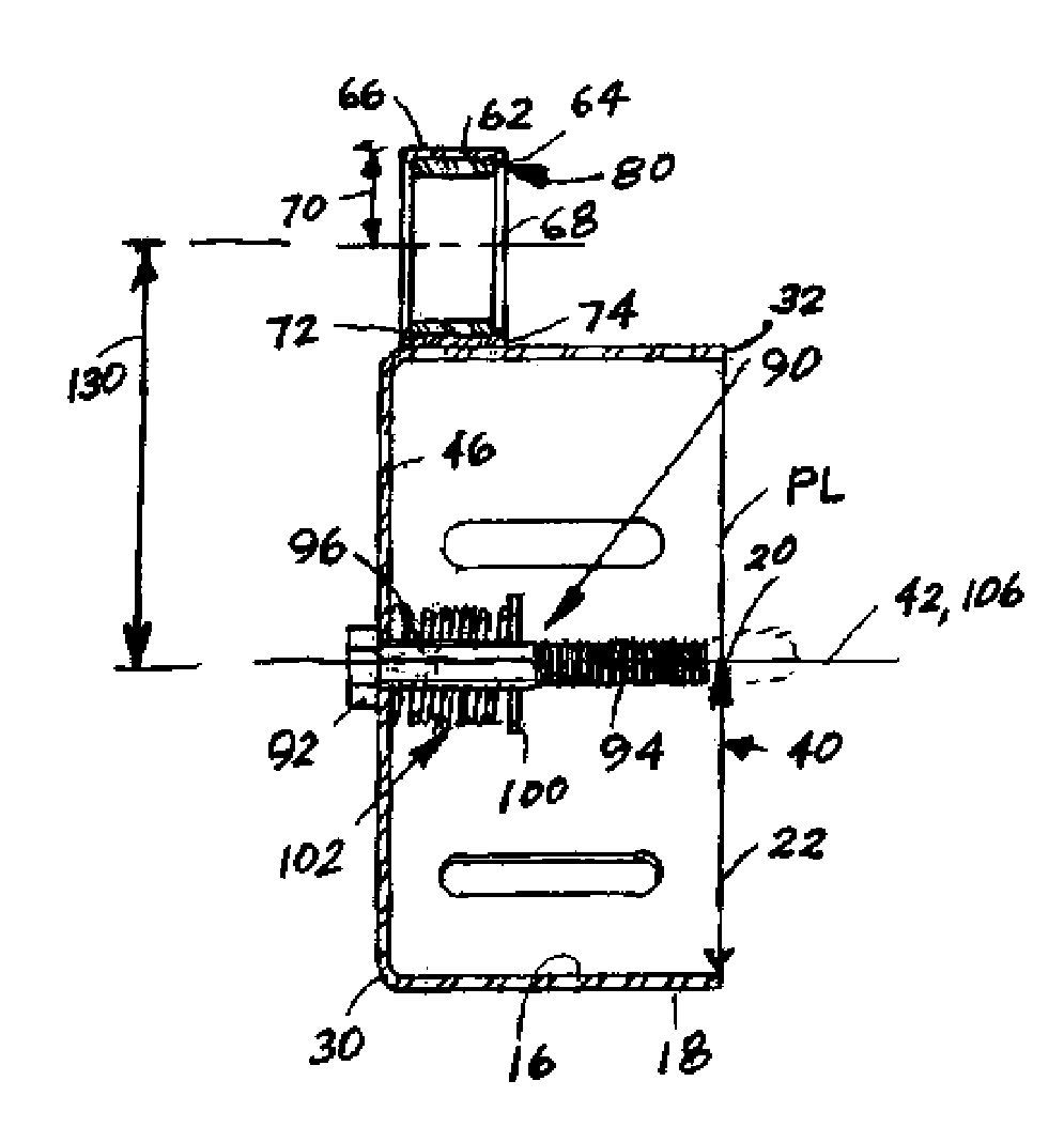
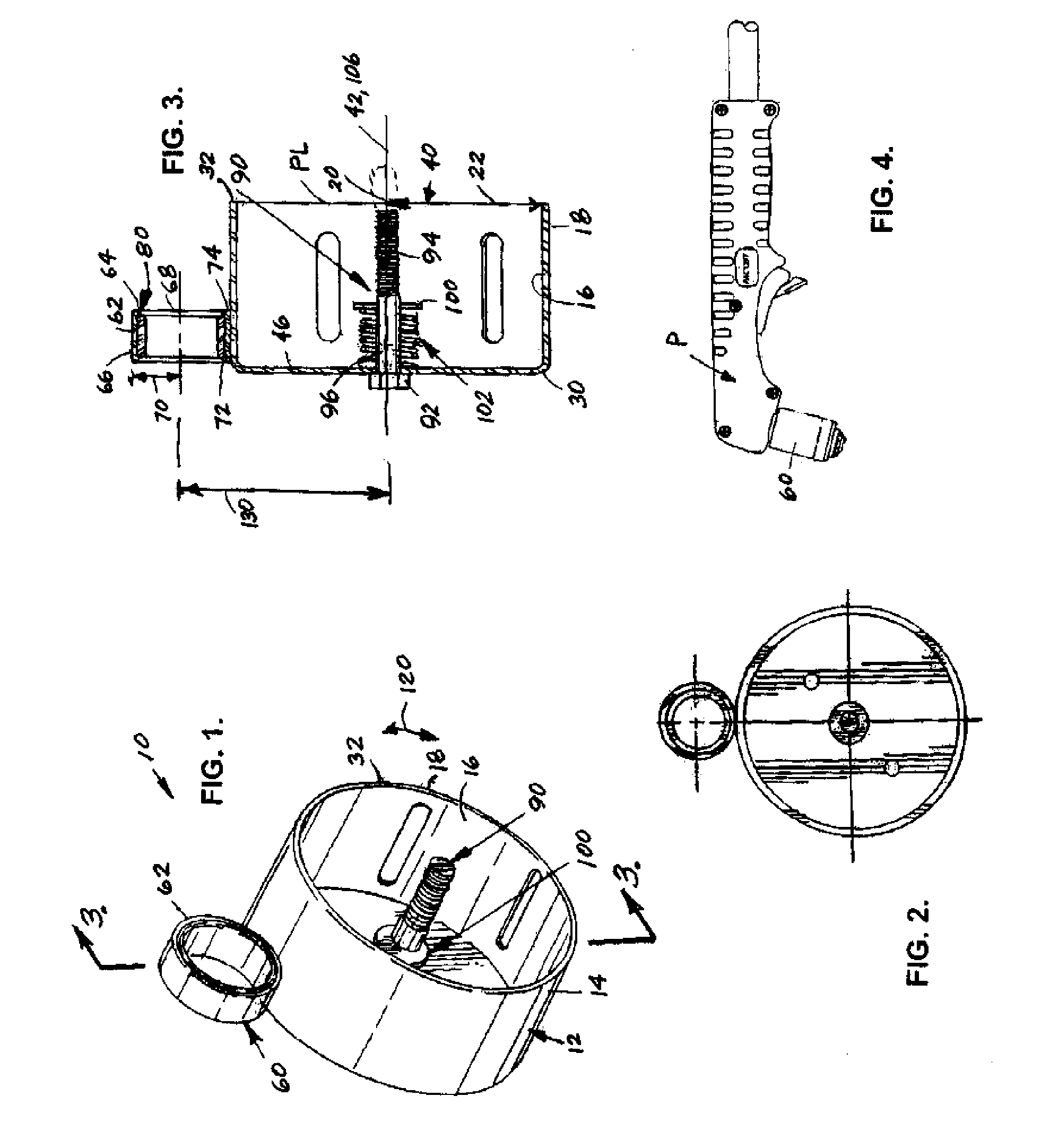
[0018]Referring to the Figures, it can be understood that the present invention is embodied in a guide 10 for use with a plasma torch and which achieves the above-stated objectives.

[0019]Guide 10 can be formed of steel or other such material and comprises a main ring 12. Main ring 12 includes a circular wall 14 which has a first surface 16, which is an inner surface when main ring 12 is in use, and a second surface 18, which is an outer surface when main ring 12 is in use. A center 20 is defined by the circular wall 14 and a radius 22 extends from center 20 to second surface 18 of circular wall 14. Main ring 12 further includes a first end 30 which is a top end when main ring 12 is in use and a second end 32 which is a bottom end when main ring 12 is in use. Second end 32 encloses an area 40. A longitudinal axis 4...


PUM

PropertyMeasurementUnit
radiusaaaaaaaaaa
areaaaaaaaaaaa
cutting radiusaaaaaaaaaa

Abstract

A guide that is used in conjunction with a plasma cutting torch includes a main circular ring having a small circular ring mounted on the outer periphery thereof. The small ring includes a bearing assembly and accommodates the plasma cutting torch. A guide bolt is mounted on the main circular ring and is attached to the workpiece and forms the center of a circular hole that will be cut with the plasma torch. Once the main ring is attached to the workpiece, the plasma torch is attached to the small ring. The torch and rings are then rotated about the bolt with the plasma torch activated to cut a hole that has a radius equal to the radius of the main circular ring plus the radius of the small ring.

Description

BACKGROUND OF THE INVENTION[0001]The present invention relates to the general art of cutting, and to the particular field of cutting with a guide.[0002]Many workers are required to cut precise and accurate holes in a workpiece. The hole can be used to accommodate wiring, conduits or the like. Sometimes, the hole must be cut into steel or other such hard substance. In such cases, the cutting tool may be expensive and the workpiece may also be very expensive. Accordingly, any errors should then be, if not totally avoided, at least minimized.[0003]Therefore, there is a need for a cutting tool that can define precise cuts in hard workpieces with a minimum of error or waste.[0004]Still further, any hole that is cut with tools known to the inventor often leaves debris or jagged edges on the workpiece. Such debris or jagged edges must be cleaned up which may be a time-consuming task.[0005]Therefore, there is a need for a cutting tool that can define precise and clean cuts in hard workpiece...

Claims


Application Information

Patent Timeline
Patent Type & Authority Patents(United States)
IPC IPC(8): B23K10/00
CPCB23K10/00B23K37/0217B23K37/027Y10T408/567Y10T408/5565
Inventor THOMPSON, ERIC Q.
Owner THOMPSON ERIC Q
Why Eureka
Try Eureka