Capping layer to impede atom ejection

a technology of a cap layer and an atom ejection, which is applied in the direction of material analysis using wave/particle radiation, optical radiation measurement, instruments, etc., can solve the problems of reducing precision and relative large error bar spread, and achieve the effect of reducing atom ejection and reducing atom ejection

Inactive Publication Date: 2006-05-23
KLA TENCOR TECH CORP
View PDF3 Cites 0 Cited by
  • Summary
  • Abstract
  • Description
  • Claims
  • Application Information

AI Technical Summary

Benefits of technology

[0006]The above and other needs are met by a method of reducing atom ejection from a sample during electron beam bombardment. An electron beam is directed through a low pressure environment toward a surface of the sample. The electron beam thereby impinges on the sample at a target location, and thereby causes characteristic x-ray emission from the target location of the sample. A capping precursor is introduced into the low pressure environment, where the capping precursor forms a capping layer on the surface of the sample at the target location when contacted by the electron beam. The capping layer thereby reduces atom ejection from the sample at the target location, while not appreciably impeding and confounding the characteristic x-ray emission from the target location of the sample.
[0007]In this manner, a capping layer is formed on the surface of the sample wherever the electron beam impinges on the sample. The capping layer reduces, and preferably eliminates the incidence of atom ejection from the sample, and thereby reduces and preferably eliminates the trending that is displayed when the electron beam impinges a given target location for an appreciable length of time. Because the trending is reduced, the readings taken using the method as described tend to be more exact. Thus, longer readings can be taken, and a higher precision in the results is attained.
[0008]In various embodiments according to this aspect of the invention, the method is implemented in an electron stimulated x-ray metrology system. Preferably, the capping layer substantially eliminates atom ejection from the sample at the target location. The capping precursor preferably includes at least one of alcohol, ketone, aldehyde, ether, ester, organic acid, organic halide, unsaturated organic molecule, organic molecule with a dipole that can form a weak bond, hydrogen bond, or van-der-Waals bond to the surface of the sample, silicon based halide, inorganic molecule capable of bonding to the surface of the sample, molecules with polar bonds such a carbon-halogen bond and silicon-halogen bond, dipoles such as unsaturated organic molecules, silicon based molecules such as SiCl4. Most preferably the capping precursor includes a short chain hydrocarbon with an oxygen functional group, such as 2-propanol.
[0010]In various embodiments according to this aspect of the invention, the apparatus is implemented in an electron stimulated x-ray metrology system. A capping precursor source is preferably connected to the injector, and holds a store of the capping precursor. The injector may be a plurality of injectors. A flow rate adjustment is preferably connected to the injector, and adjusts a flow rate of the capping precursor. In one embodiment, the injector is disposed to inject the capping precursor at the target location. The capping layer preferably substantially eliminates atom ejection from the sample at the target location. The capping precursor preferably includes a short chain hydrocarbon and an oxygen functional group.

Problems solved by technology

Unfortunately, there are some problems with the technique.
However, a short acquisition time tends to result in a relatively large error bar spread.
Thus, while repeated measurements at different points tend to result in a reduced precision, trending causes repeated measurements at the same point to result in a precision that is even further reduced.

Method used


Image

  • Capping layer to impede atom ejection
  • Capping layer to impede atom ejection

Examples


Embodiment Construction

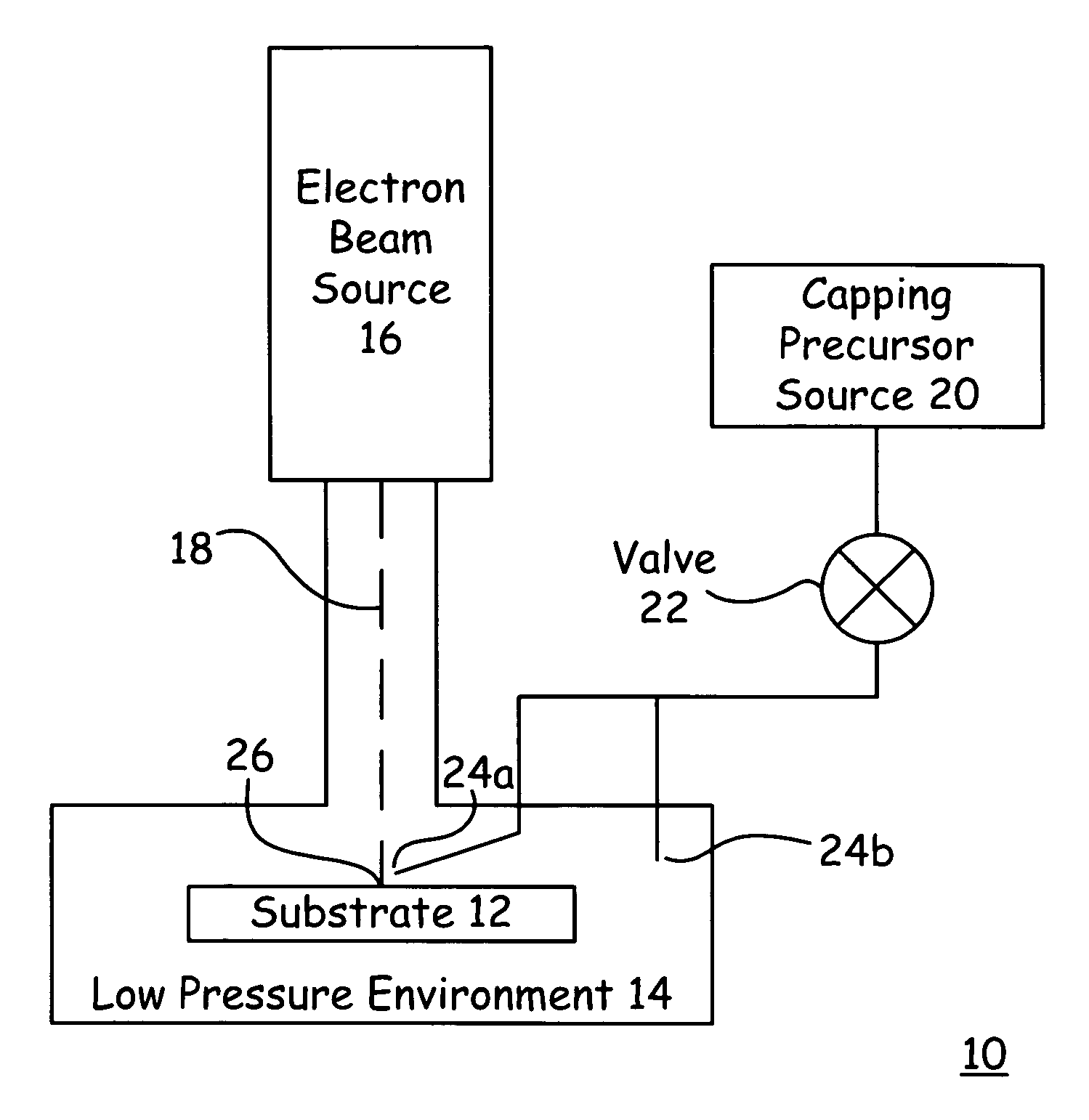
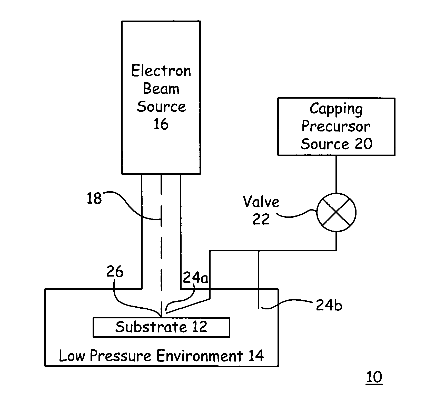
[0014]With reference now to the FIGURE, there is depicted a functional block diagram of a system 10 according to a preferred embodiment of the present invention. The system 10 is preferably implanted as an electron stimulated x-ray metrology system, and thus includes the components and subsystems as are traditionally included with such a system, some of which are not depicted in the FIGURE so as to more completely focus attention on the more novel aspects of the system 10. The system 10 preferably includes an electron beam source 16 which directs an electron beam 18 toward a target location 26 on a substrate 12. Preferably, at least the electron beam 18 and the target location 26 of the substrate 12 are disposed within a low pressure environment 14.

[0015]A capping precursor source 20 preferably holds a store of a capping precursor, which has properties as described more completely below. The capping precursor is preferably introduced to the low pressure environment 14 through one or...


PUM

PropertyMeasurementUnit
pressureaaaaaaaaaa
flow rateaaaaaaaaaa
electron beam stimulated x-ray analysisaaaaaaaaaa

Abstract

A method of reducing atom ejection from a sample during electron beam bombardment. An electron beam is directed through a low pressure environment toward a surface of the sample. The electron beam thereby impinges on the sample at a target location, and thereby causes characteristic x-ray emission from the target location of the sample. A capping precursor is introduced into the low pressure environment, where the capping precursor forms a capping layer on the surface of the sample at the target location when contacted by the electron beam. The capping layer thereby reduces atom ejection from the sample at the target location, while not appreciably impeding and confounding the characteristic x-ray emission from the target location of the sample.

Description

FIELD[0001]This invention relates to the field of integrated circuit fabrication. More particularly, this invention relates to electron beam stimulated x-ray analysis of integrated circuit layers.BACKGROUND[0002]Integrated circuit fabrication is typically accomplished by forming many different layers on a substrate. As the term is used herein, “integrated circuit” includes devices such as those formed on monolithic semiconducting substrates, such as those formed of group IV materials like silicon or germanium, or group III–V compounds like gallium arsenide, InP, or mixtures of such materials. The term includes all types of devices formed, such as memory and logic, and all designs of such devices, such as MOS and bipolar. The term also comprehends applications such as flat panel displays, solar cells, and charge coupled devices. Because the design tolerances of an integrated circuit are so strict, it is desirable to monitor the properties, such as thickness and elemental composition,...

Claims


Application Information

Patent Timeline
Patent Type & Authority Patents(United States)
IPC IPC(8): G01N23/223
CPCG01N23/2252H01J2237/25H01J2237/24415
Inventor SOLTZ, DAVID AITAN
Owner KLA TENCOR TECH CORP
Why Eureka
Try Eureka