Image reading method and image recording and reading device

Inactive Publication Date: 2006-05-23
FUJIFILM CORP +1
View PDF19 Cites 31 Cited by
  • Summary
  • Abstract
  • Description
  • Claims
  • Application Information

AI Technical Summary

Benefits of technology

[0044]According to the first image reading method of the present invention and the first and third image recording and reading devices of the present invention, the correction region is set as the correction pixel region formed in units of pixels, a plurality of the correction pixel regions are provided so as to be dispersed and distributed in the area where the recording electromagnetic wave is irradiated, and the respective image signals read from the read pixels positioned in the region other than the correction pixel regions are corrected based on the correction region signals read from the correction pixel regions located in the vicinity of the respective read pixels. Thus, the offset, gain and the like attributable to the dark current can be corrected more accurately and easily.
[0045]Moreover, in the foregoing first image reading method and the first and third image recording and reading devices, when the correction pixel region is provided so as to be adjacent to each read pixel and the correcting means corrects each image signal read from the read pixel based on the correction region signal read from the correction pixel region adjacent to each read pixel, the read pixel and the correction pixel exist in positions closer to each other, thus enabling more accurate correction.
[0046]Moreover, when the co

Problems solved by technology

Due to this dark current, a stationary gain or offset is included in an image signal outputted from the radiation solid-state detector, and thus a reproduced image based on an accurate image signal cannot be obtained.
In addition, there a problem arises in that deterioration in an image qual

Method used


Image

  • Image reading method and image recording and reading device
  • Image reading method and image recording and reading device
  • Image reading method and image recording and reading device

Examples


first embodiment

[0087]According to the radiation image recording and reading device of the foregoing first embodiment, the correction pixel regions are provided so as to be adjacent to the read pixels, and the correcting means 25 corrects the image signals corresponding to the read pixels based on the correction region signals corresponding to the correction pixel regions adjacent to the read pixels. Thus, an offset, a gain and the like attributable to a dark current can be corrected more accurately and easily.

[0088]Moreover, when the correcting means 25 obtains the image signals corresponding to the correction pixel regions by interpolation thereof using the image signals of the read pixels after the correction, which are positioned in the periphery of the image signals corresponding to the correction pixel regions, appropriate image signals are also calculated for the correction pixel regions. Thus, deterioration of an image quality due to the provision of the correction pixel regions can be supp...

second embodiment

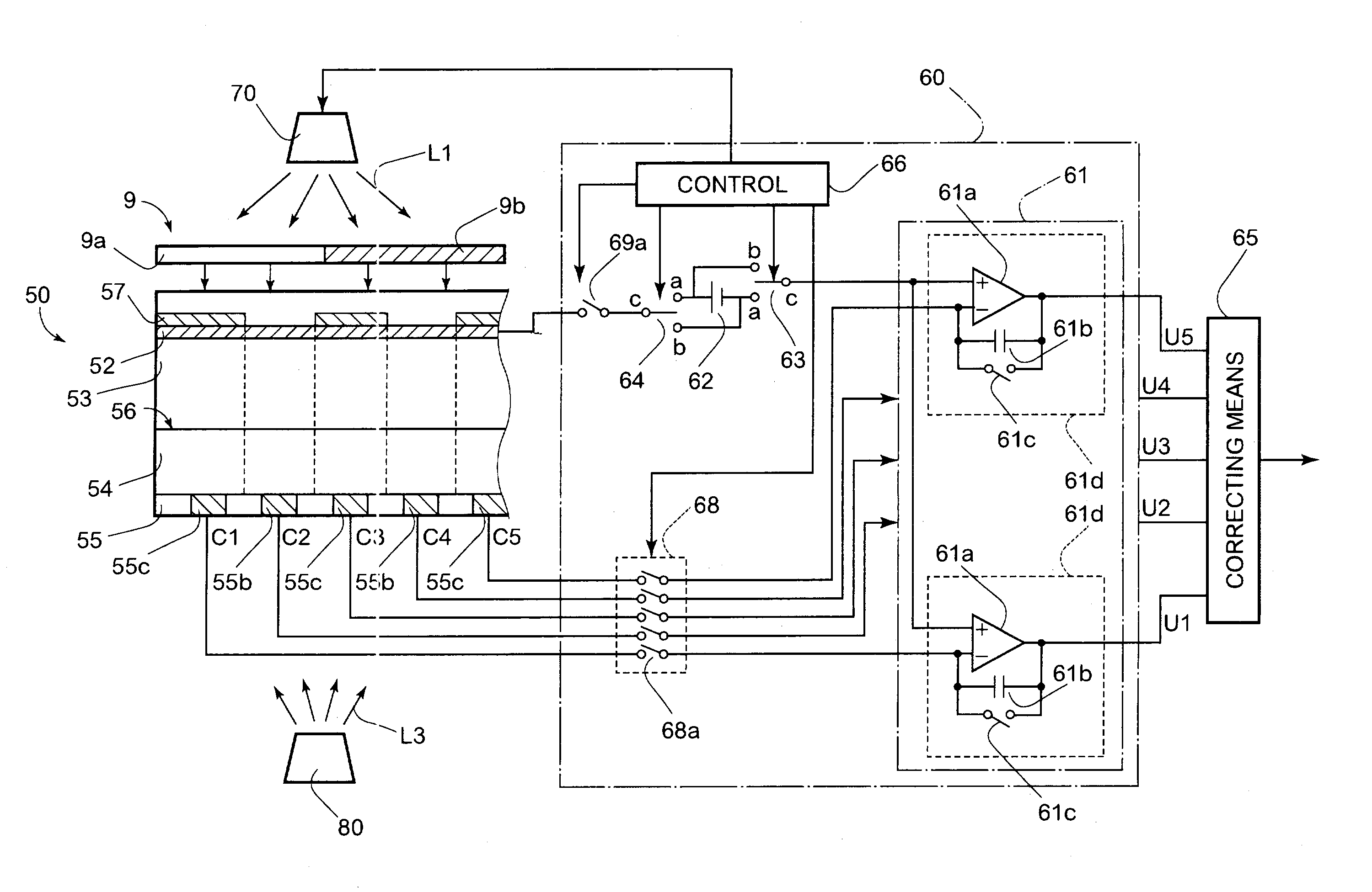
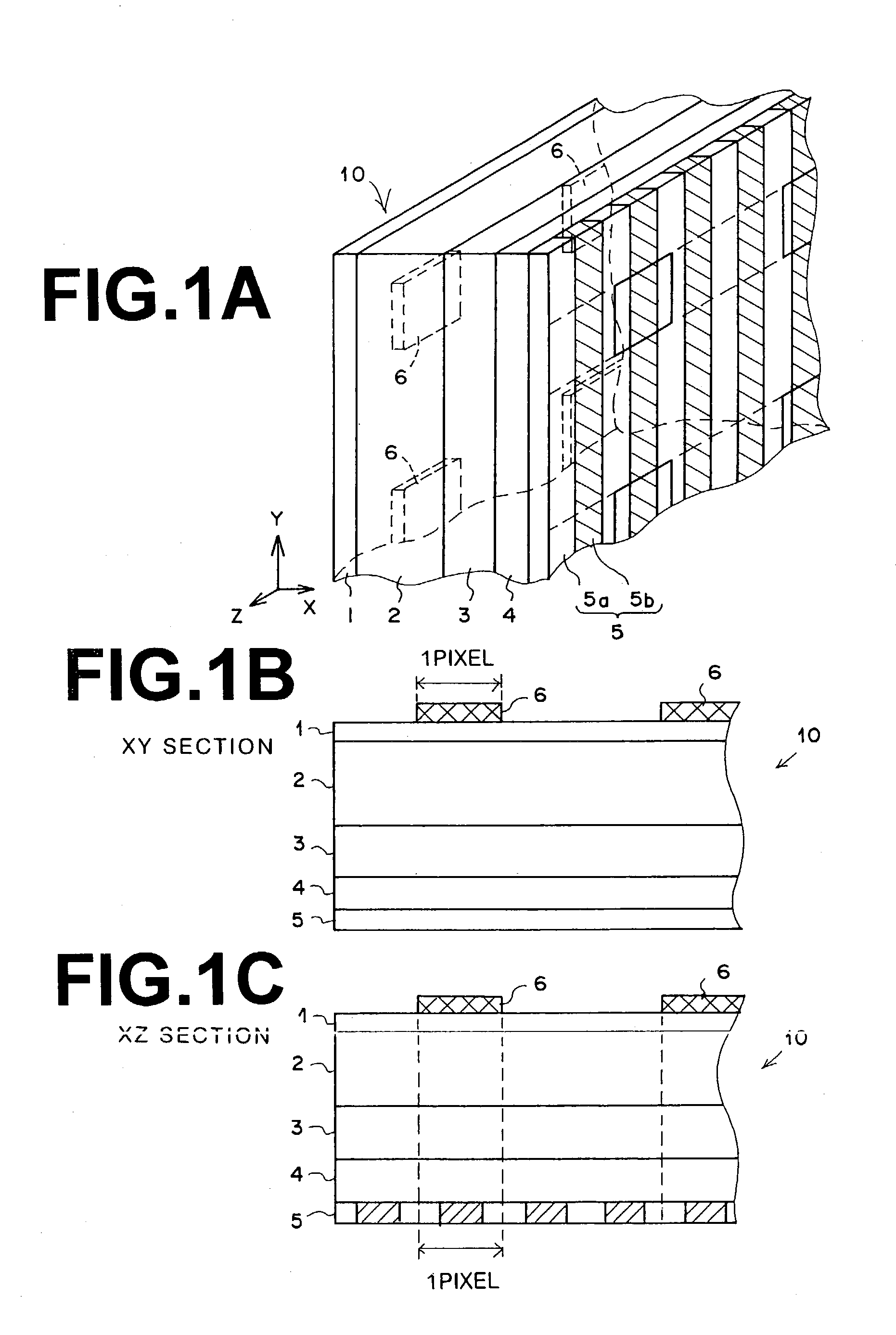
[0089]Next, description will be made for an image recording and reading device implementing an image reading method of the present invention. FIGS. 7A through 7C are views showing a schematic configuration of a radiation solid-state detector used in this embodiment. FIG. 7A is a perspective view thereof, FIG. 7B is an X-Y section view thereof and FIG. 7C is an X-Z section view thereof.

[0090]A radiation solid-state detector 50 records radiation image information as a static latent image and generates a current corresponding to the foregoing static latent image by being scanned with a reading electromagnetic wave (hereinafter referred to as a reading light). Specifically, the radiation solid-state detector 50 is constituted by sequentially laminating the following layers, including: a phosphor 51 emitting a fluorescence L4 upon excitation of a recording light L2; a first electrode layer 52 having first stripe electrodes, which are formed therein by arranging a number of tabular elemen...


PUM


Abstract

In a radiation image reading method for reading image signals corresponding to radiation image information from a radiation solid-state detector in which the radiation image information is recorded by irradiation of a recording electromagnetic wave, correction of an offset and a gain in the image signals, which are attributable to a dark current of the radiation solid-state detector, is performed more accurately and easily. A correction pixel region, in which a light-shielding member 6 is provided so as to be adjacent to respective read pixels, and a correcting means 25 corrects an image signal corresponding to the read pixel based on a correction region signal corresponding to the correction pixel region adjacent to the read pixel.

Description

BACKGROUND OF THE INVENTION[0001]1. Field of the Invention[0002]The present invention relates to an image reading method for reading an image signal corresponding to image information from a solid-state detector in which the image information is recorded by irradiation of a recording electromagnetic wave, and to an image recording and reading device using the foregoing solid-state detector.[0003]2. Description of the Related Art[0004]Nowadays, in radiography for the purpose of medical diagnosis and the like, a radiation image recording and reading device is known, which uses a radiation solid-state detector for detecting radiation and outputting an image signal representing radiation image information. Various types of detectors are proposed and put to practical use as the detector used in the above device.[0005]From the aspect of a charge generation process for converting radiation into electric charges, for example, there are radiation solid-state detectors of the following types,...

Claims


Application Information

Patent Timeline
IPC IPC(8): G01T1/24G06T1/00G03B42/02H01L27/146H04N1/04
CPCH04N5/361H01L27/14658H04N25/63
Inventor AGANO, TOSHITAKA
Owner FUJIFILM CORP
Why Eureka
Try Eureka