
Determination of borehole geometry inside cased wells with crosswell electromagnetics

a crosswell electromagnetic and geometry technology, applied in wave based measurement systems, instruments, reradiation, etc., can solve problems such as variable and inconsistent cable loading, actual amount of cable stretching may vary, and problems are encountered

Active Publication Date: 2006-05-23
SCHLUMBERGER TECH CORP
View PDF10 Cites 6 Cited by
  • Summary
  • Abstract
  • Description
  • Claims
  • Application Information

AI Technical Summary

Benefits of technology

The patent text describes methods for locating a receiver in a borehole with a conductive liner using an electromagnetic field induced from a transmitter in another borehole. The methods also involve detecting the induced electromagnetic field at different locations in the borehole and calculating the geometry coordinates based on the detected responses. These methods can be used to map the trajectory of a cased wellbore and the surrounding earth formation. The technical effects of the patent text include improved wellbore construction and mapping of the wellbore trajectory for better wellbore placement and drilling.

Problems solved by technology

Even with very elaborate compensation algorithms, however, the actual amount of cable stretching may vary over time and because of unforeseen and unmeasured interactions between the cable and tool string and the well bore (such as tool hang-ups and cable friction) and anomalies such as cable “bounce”.
Deviated wells, in which the tool is pulled along the interior surface of the well casing, can present particular problems with variable and inconsistent cable loading, as the stool “sticks” and jumps along the well bore.
Such problems are also encountered albeit to a lesser degree, in tubing-conveyed operations in which tubing length is measured by a wheel arranged to roll along the tubing as it is unspoiled.
Even very small deployment length measurement error percentages and other discrepancies can result, with either type of deployment, in absolute tool positioning errors of several feet or more in a well of over a mile in depth, for example.
Use of downhole sensors is challenging and present even more difficulties in the case of completed wells, in which the casing effects the ability to run certain downhole sensors.
The conductive tubular liners interfere with resistivity measurements and are difficult and costly to remove from the borehole once they are installed.
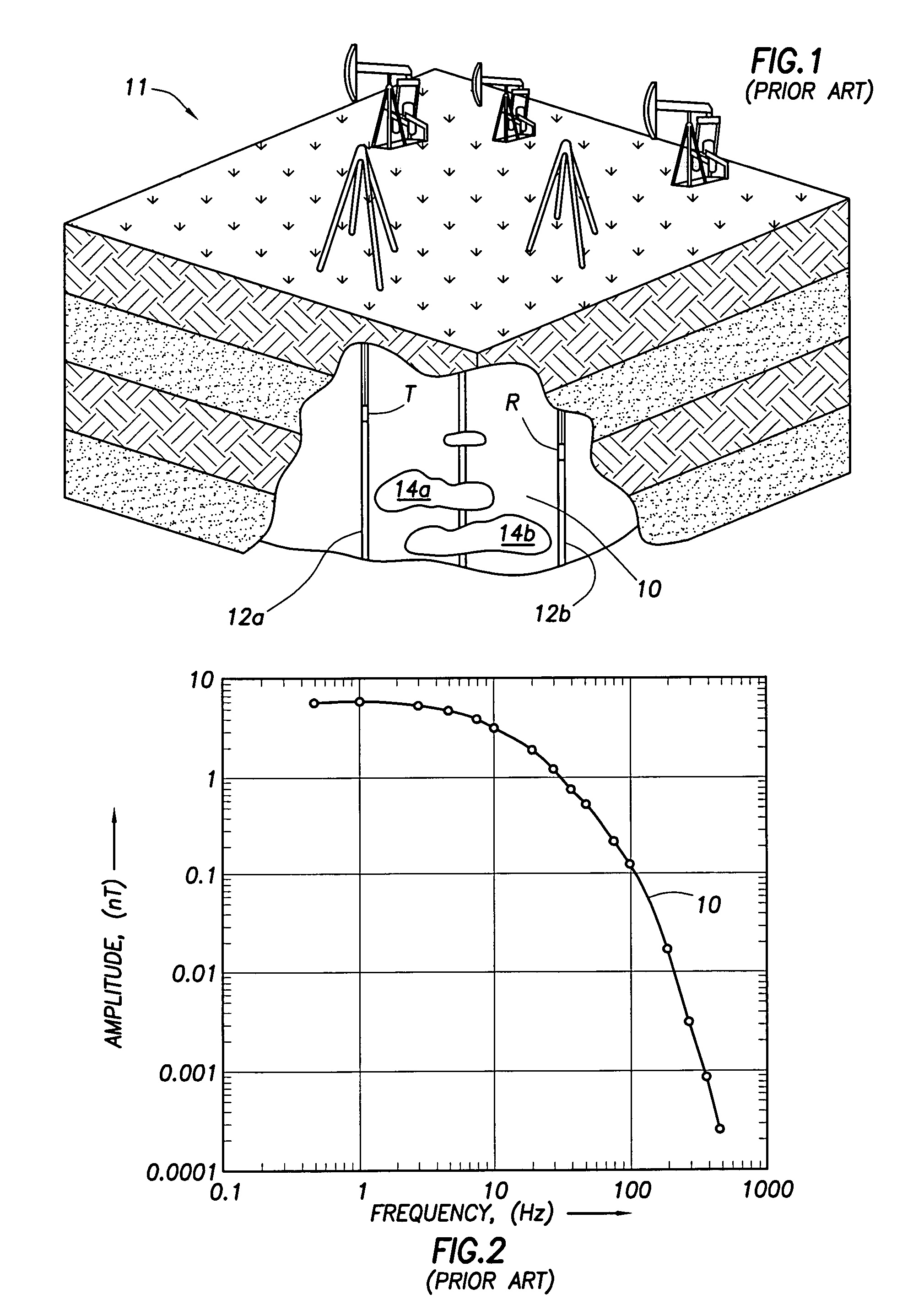
As a result, prior art systems such as that shown in FIG. 1 are not suitable for analyzing hydrocarbon reservoirs once extraction of the hydrocarbons begins.
Often the design criteria for a crosshole survey of a cased borehole reduces the signal to a level that is undetectable by standard receivers.
Moreover, the variance in conductivity, permeability, and thickness along a longitudinal axis of a liner makes difficult determining the attenuation factor at any given point.

Method used


Image

  • Determination of borehole geometry inside cased wells with crosswell electromagnetics
  • Determination of borehole geometry inside cased wells with crosswell electromagnetics
  • Determination of borehole geometry inside cased wells with crosswell electromagnetics

Examples


Embodiment Construction

[0026]According to an embodiment of the disclosed subject matter, a regularized inversion formulation removes the casing effects from field data to yield a data set equivalent to one that would be obtained in uncased well. The solution obtained is dependent on the geometry of the survey and the conductivity of the formation being measured.

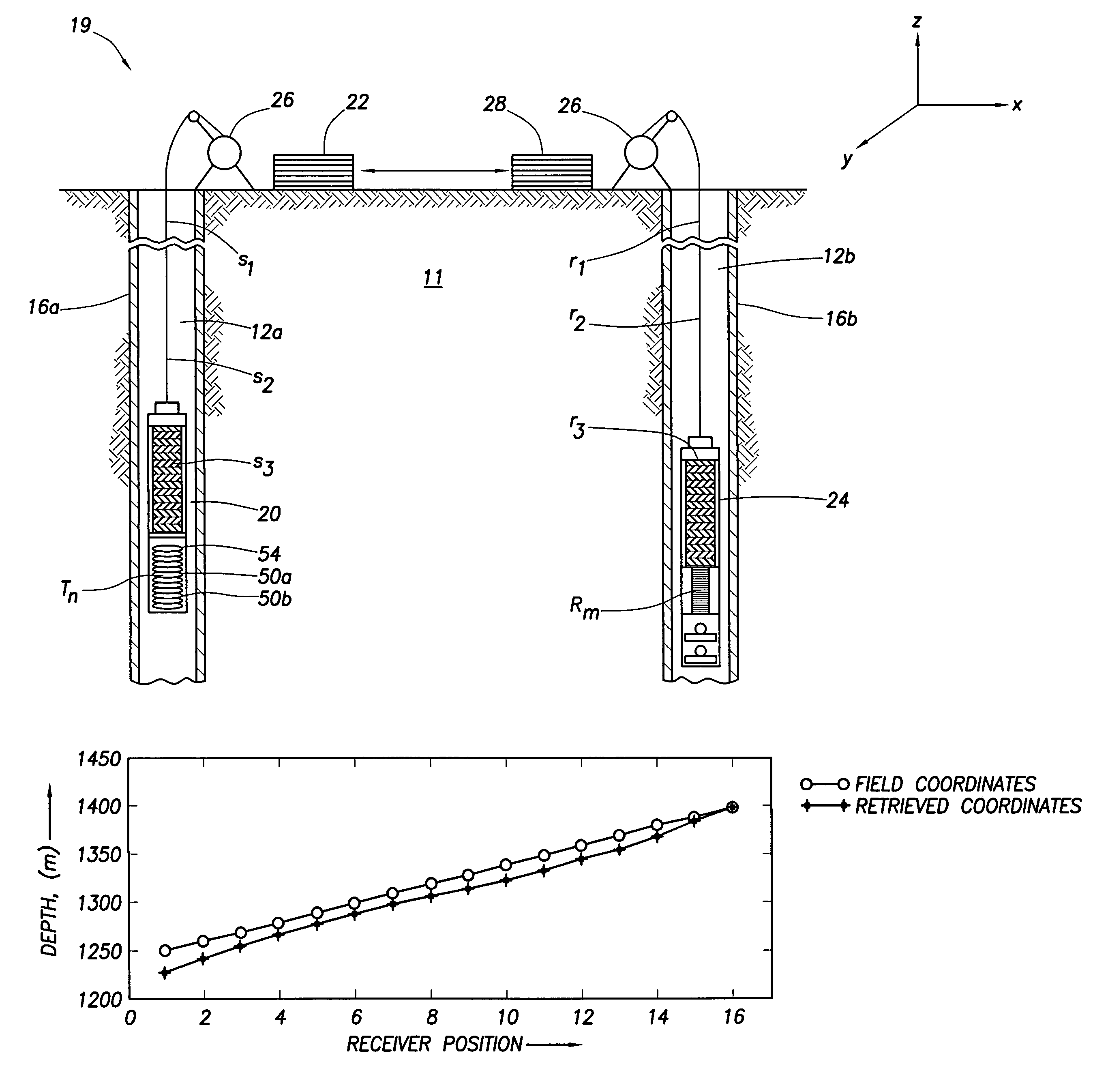
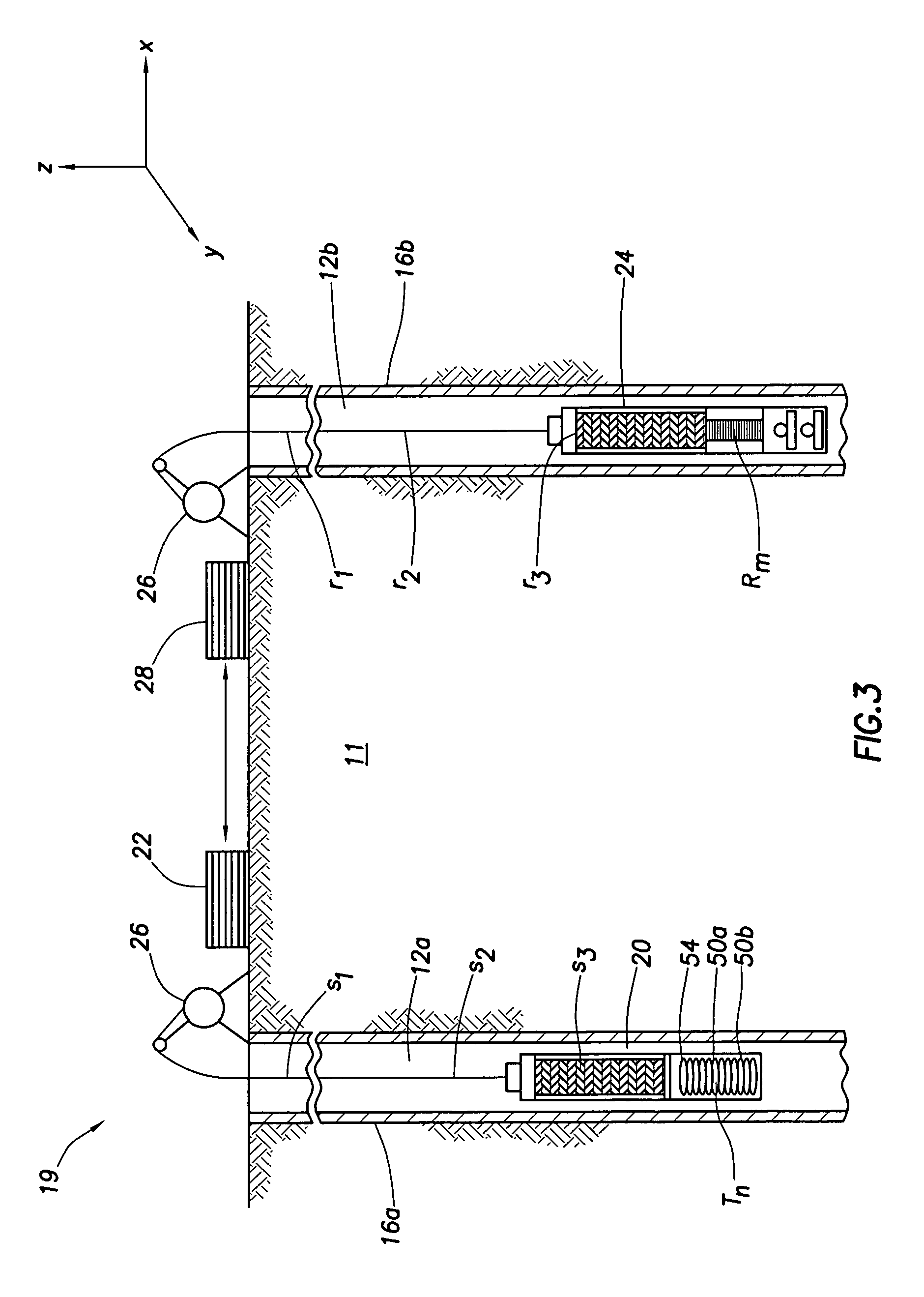
[0027]Referring to FIG. 1, a geologic formation 11 under analysis includes one or more boreholes, shown generally as 12a and 12b and a reservoir of resources of interests, in this example one or more reservoirs of hydrocarbons, shown generally as 14a and 14b. Typically, at least one of the boreholes 12a and 12b is cased with a conductive liner 16a and 16b, shown more clearly in FIG. 3. A system 19 employed to analyze the geologic formation includes a transmitter 20 disposed within borehole 12a, a first region of the geologic formation. In signal communication with the transmitter 20 is a signal generator included in surface station 22. A receiver 2...


PUM


Abstract

A method is disclosed for locating a receiver in a borehole having a conductive liner by inducing an electromagnetic field from a transmitter in a first borehole, detecting at a first location by at least one receiver located in a second borehole having a conductive liner, a first electromagnetic field induced by the transmitter, detecting at a second location by the at least one receiver, a second electromagnetic field induced by the transmitter and calculating a set of geometry coordinates for the first location based on the first electromagnetic field and the second electromagnetic field.

Description

BACKGROUND OF INVENTION[0001]In performing operations within a cased well, such as logging formation properties, it is important to know the exact location of the tool lowered into the well to perform the specific function. Measuring the depth of well logging tools is traditionally made from the surface, by measuring how much of the cable which supports the tools has been deployed. Both wireline tools and while-drilling tools rely on the same basic concept.[0002]The depth of the tool string is commonly determined by passing the cable over a calibrated measurement wheel at the surface of the well. As the tool is deployed, the length of cable unspoiled into the well is monitored as an estimate of tool depth. Depth compensation for cable stretch may be attempted by calculating a theoretical stretch ration based upon cable length, elasticity and tool weight. Even with very elaborate compensation algorithms, however, the actual amount of cable stretching may vary over time and because of...

Claims


Application Information

Patent Timeline
Patent Type & Authority Patents(United States)
IPC IPC(8): G01V3/08G01V3/26E21B47/092
CPCG01V3/26
Inventor HABER, ELDADZHANG, PING
Owner SCHLUMBERGER TECH CORP
Learn More