
Call management system using dynamic queue position

a call management system and dynamic queue technology, applied in the field of call centers, can solve the problems of inability to achieve the desired service level for each of the call types supported by the call center, inability to meet the needs of callers, etc., and achieve the effect of high degree of accuracy

Inactive Publication Date: 2006-05-23
AVAYA INC
View PDF7 Cites 247 Cited by
  • Summary
  • Abstract
  • Description
  • Claims
  • Application Information

AI Technical Summary

Benefits of technology

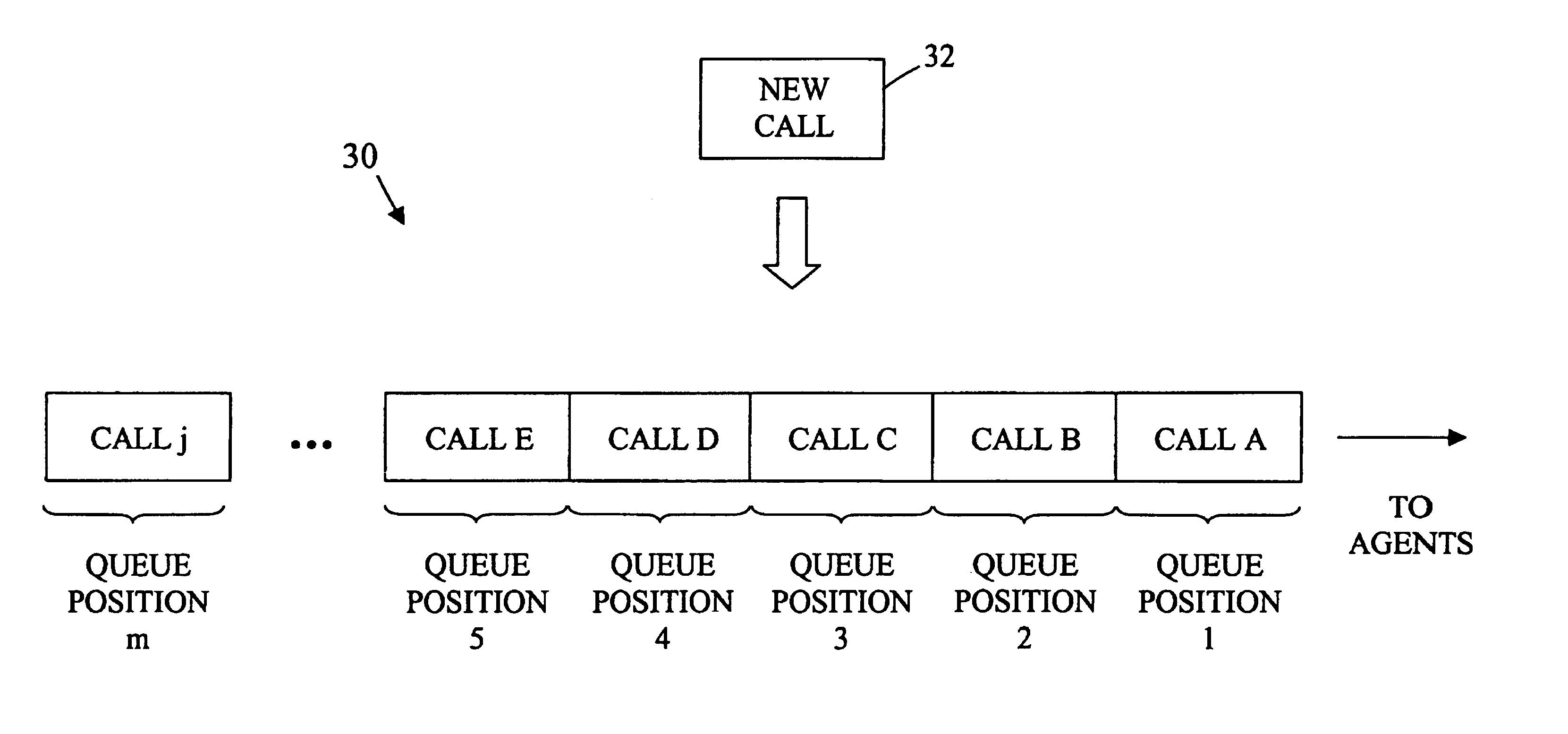
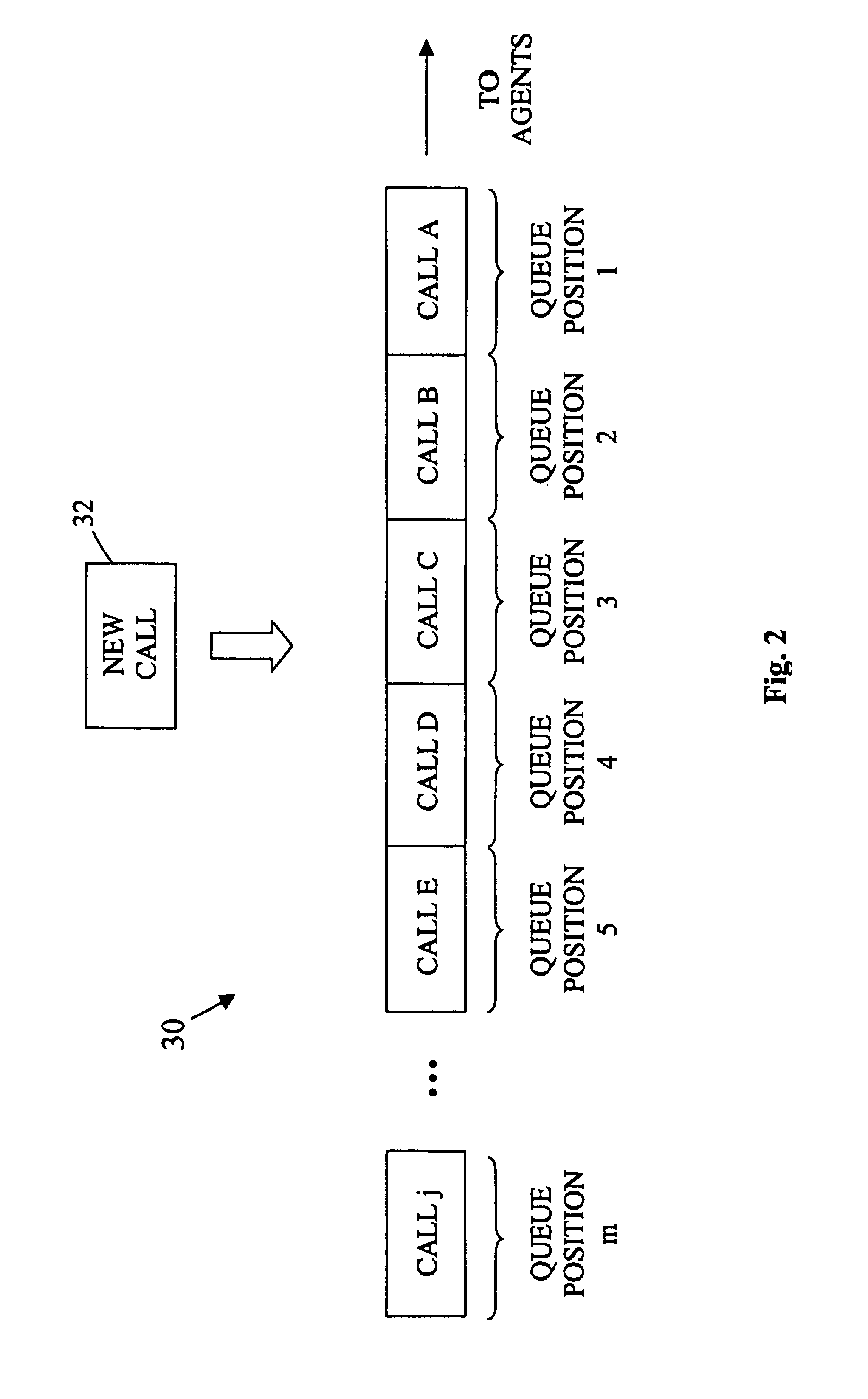
[0005]The present invention relates to a system for use within a call center that dynamically positions newly received calls, having a number of different call types, within a single call queue to be addressed by agents within the call center. The system positions a new call within the queue based on, among other things, a service level objective associated with the new call and an amount of time that calls already within the queue have been waiting to be answered. Because the system takes into account the amount of time that other calls have been waiting to determine the queue position of the new call, less important calls are not left waiting indefinitely when a continuous stream of more important calls is being received by the call center. In addition, because the service level objectives associated with the incoming calls are also considered in the positioning decision, the system is capable of achieving service level target values to a relatively high degree of accuracy.

Problems solved by technology

However, past techniques for achieving the desired service levels for each of the call types supported by the call center have generally been inadequate.
Therefore, if high priority calls are continually being received by the system, the lower priority calls within the queue can remain unanswered for an indefinite period of time.
Such calls are often abandoned in frustration by corresponding callers.

Method used


Image

  • Call management system using dynamic queue position
  • Call management system using dynamic queue position
  • Call management system using dynamic queue position

Examples


Embodiment Construction

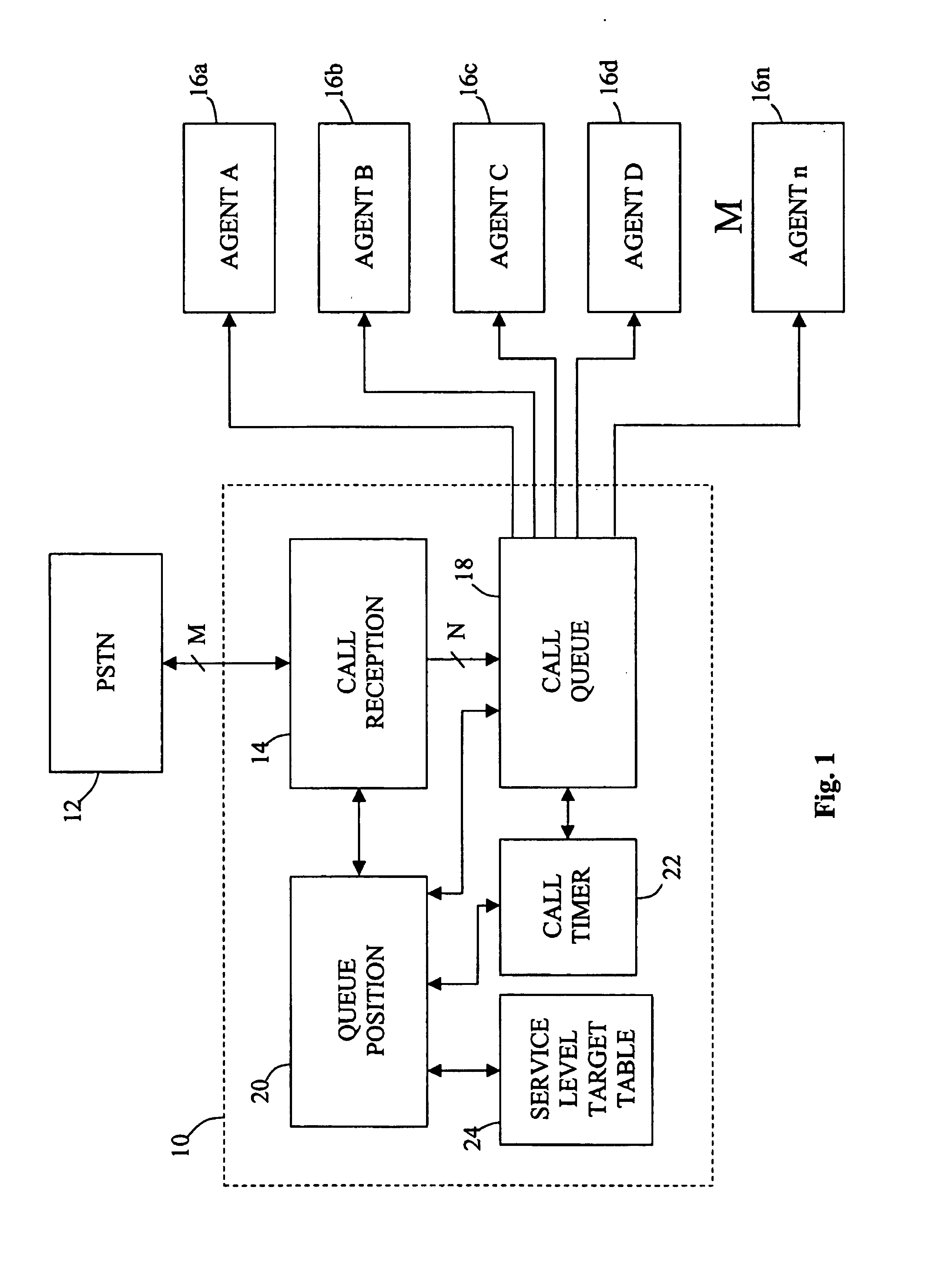
[0013]FIG. 1 is a block diagram illustrating a call center 10 in accordance with one embodiment of the present invention. The call center 10 can be used, for example, to service telephone calls coming into an organization or business. As illustrated, the call center 10 is coupled to a public switched telephone network (PSTN) 12 from which it receives incoming telephone calls from a plurality of remote entities. The call center 10 is also coupled to a plurality of agent stations 16a, 16b, 16c, 16d, . . . , 16n at which a number of human agents are positioned for handling calls received by the call center 10. The agent stations 16a, 16b, 16c, 16d, . . . , 16n can each include, for example, a desktop computer unit and a telephone headset to be worn by a corresponding agent.

[0014]The call center 10 receives calls from the PSTN 12 having a plurality of different call types. Each of the different call types has a service level target value associated with it that describes a desired servi...


PUM


Abstract

A call center includes functionality for dynamically positioning newly received calls within an established call queue. The calls are positioned within the queue based on predefined service objectives for call types supported by the call center and a length of time that other calls have already been waiting in the queue. In a preferred embodiment, when a new call is received by the call center, an analysis is performed for individual queue positions within the queue until a queue position is identified that meets a predetermined selection criterion. The new call is then placed within this queue position and subsequent calls within the queue are moved accordingly.

Description

TECHNICAL FIELD[0001]The invention relates generally to call centers and, more particularly, to call management techniques for use in call centers.BACKGROUND OF THE INVENTION[0002]A call center is a facility that processes telephone calls for an organization, usually using some level of computer control. Typically, the telephone calls handled by a call center are incoming calls from present or potential customers of the organization. The incoming calls are distributed among a number of agents within the call center who are each trained to handle certain types of incoming calls. A single call center will often support a large number of different call types. For example, a call center may be set up to receive calls relating to each of a multitude of different products, product types, or product families sold by the organization. Alternatively, or in addition, a call center might handle calls relating to different services or information dissemination functions provided by the organiza...

Claims


Application Information

Patent Timeline
IPC IPC(8): H04M3/00H04M11/00H04M3/42H04M3/523
CPCH04M3/5232H04M3/5238H04M3/5235H04M11/00
Inventor JENSEN, ROY A.
Owner AVAYA INC
Learn More