
Polarization-maintaining optical fiber and polarization-maintaining optical fiber component

a technology of polarization-maintaining optical fibers and components, applied in the direction of optical fibers with polarisation, instruments, optical waveguide light guides, etc., can solve the problems of bending of polarization-maintaining optical fibers and optical couplings to high-order modes, increasing excess loss, and frequent light leakage from the core, etc., to achieve excellent polarization-maintaining, small excess loss, and small excess loss

Inactive Publication Date: 2006-05-23
THE FUJIKURA CABLE WORKS LTD
View PDF24 Cites 9 Cited by
  • Summary
  • Abstract
  • Description
  • Claims
  • Application Information

AI Technical Summary

Benefits of technology

[0018]Accordingly, it is an object of the present invention to provide a polarization-maintaining optical fiber component which suppresses coupling of propagating light to a high-order mode at the optical coupling section of the polarization-maintaining optical fiber component, caused by differences in refractive index between the stress applying sections and the cladding, thus reducing excess loss.
[0019]It is another object of this invention to provide a polarization-maintaining optical fiber component by easily adjusting the polarization axis using a conventional polarization axis adjusting scheme.

Problems solved by technology

Under this situation, because the single mode condition for the polarization-maintaining optical fiber is not satisfied, the bending of the polarization-maintaining optical fiber and optical coupling to a high-order mode occur due to an unevenness factor in the polarization-maintaining optical fiber.
This increases the excess loss.
This problem occurs prominently in the light along the fast axis where light leaks from the core occur frequently.
As both refractive indexes are matched with each other in this method, however, it is difficult to observe the positions of the stress applying sections based on a difference in refractive index so that the aforementioned method of adjusting the polarization axis cannot be used.

Method used


Image

  • Polarization-maintaining optical fiber and polarization-maintaining optical fiber component
  • Polarization-maintaining optical fiber and polarization-maintaining optical fiber component
  • Polarization-maintaining optical fiber and polarization-maintaining optical fiber component

Examples


embodiments

[0065]Embodiments of this invention will now be discussed in detail.

first embodiment

(First Embodiment)

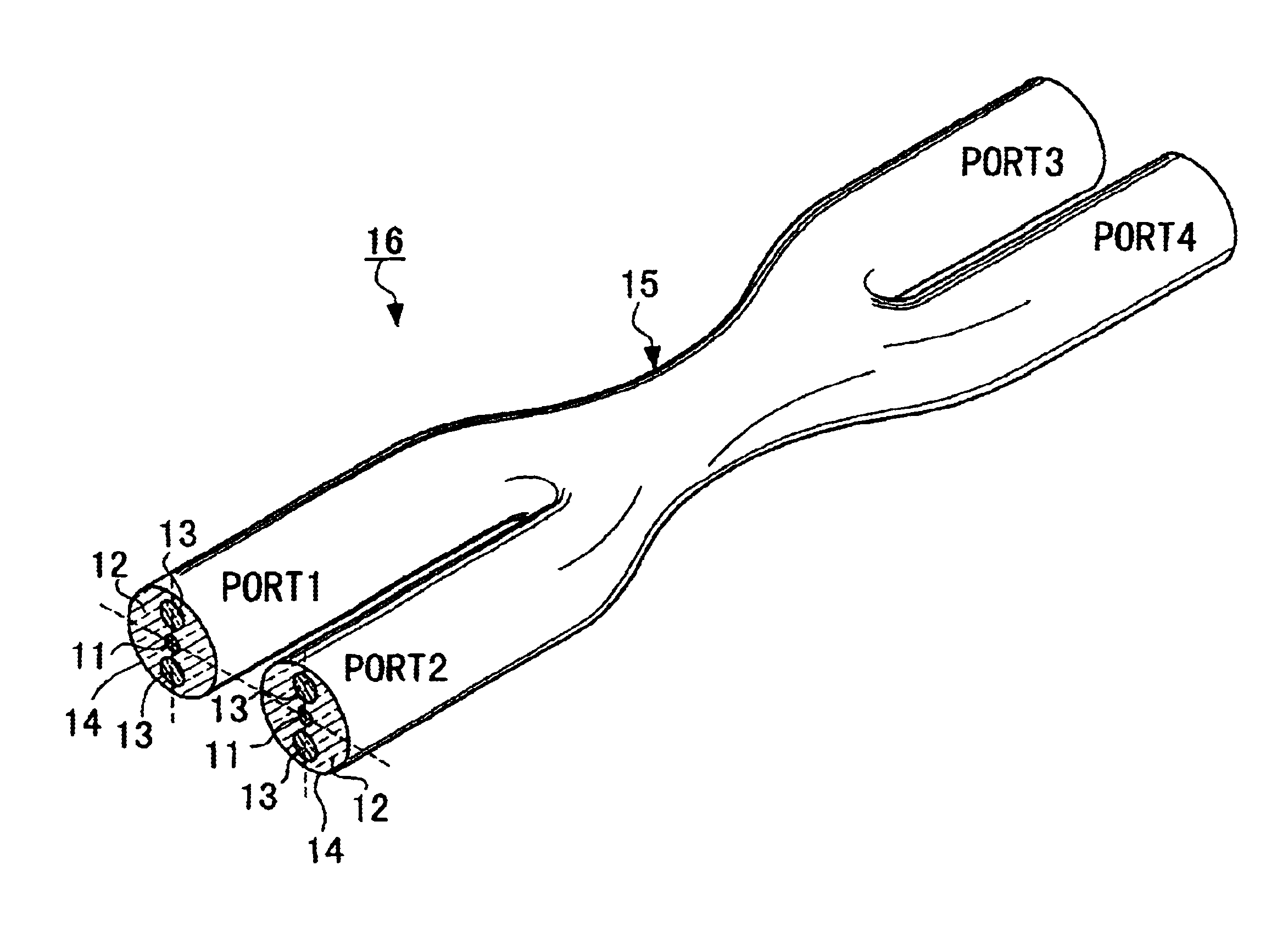
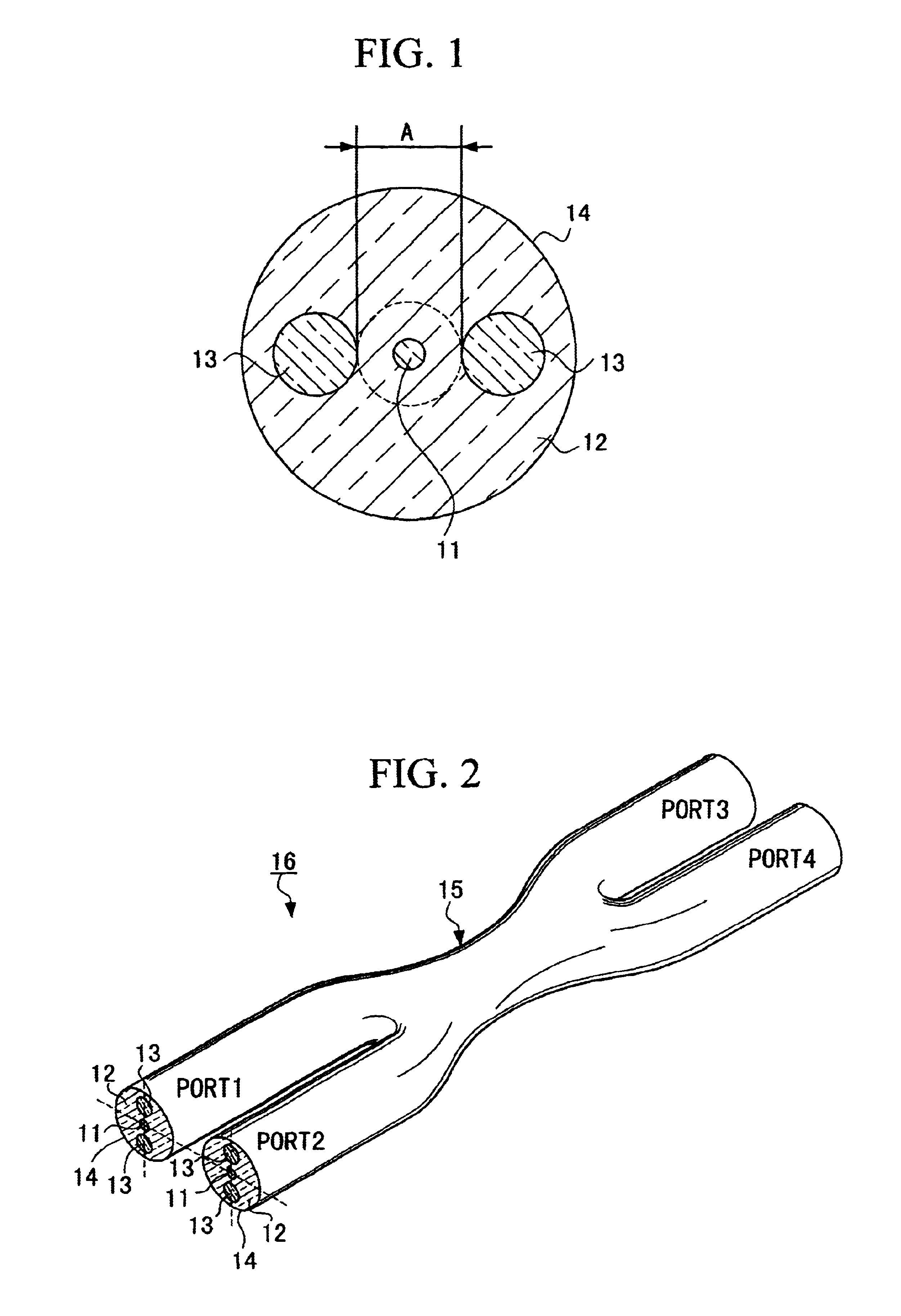
[0066]Two PANDA fibers having a diameter A of 22 μm were laid side by side and their lengthwise portions were heated and fused. Then, fiber elongation was carried out in the lengthwise direction while monitoring only the light along the fast axis and was stopped when the coupling ratio of two light-emerging ports became 50%, thus forming the optical coupling section 15. This completed a 2×2 polarization-maintaining optical fiber coupler.

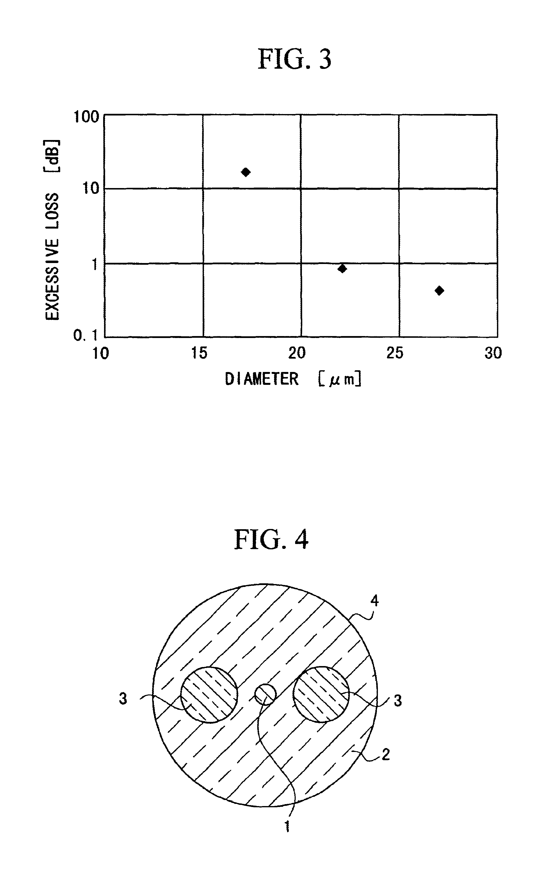
[0067]Then, the light loss of this polarization-maintaining optical fiber coupler along the fast axis was measured by the cutback scheme. The light loss along the fast axis then was 0.8 dB.

second embodiment

(Second Embodiment)

[0068]A polarization-maintaining optical fiber coupler according to the second embodiment was prepared in the same way as for the first embodiment, except that the diameter A was set to 27 μm, and the light loss of this polarization-maintaining optical fiber coupler along the fast axis was measured.

[0069]The light loss along the fast axis then was 0.4 dB.


PUM


Abstract

A polarization-maintaining optical fiber component which suppresses coupling of propagating light to a high-order mode at the optical coupling section of the polarization-maintaining optical fiber component, caused by different refractive indexes between the stress applying sections and the cladding, thus reducing excess loss, is constructed by using a polarization-maintaining optical fiber having stress applying sections arranged symmetrically to each other with respect to a core in a cladding surrounding the core, wherein the largest one of those concentric circles of the core or the said cladding which do not reach the stress applying sections and do not include the stress applying sections within has a diameter of 20 μm or greater.

Description

BACKGROUND OF THE INVENTION[0001]1. Field of the Invention[0002]The present invention relates to polarization-maintaining optical fiber components which is useful in the optical fiber communication field, the field of sensors using optical fibers and the like, such as a polarization-maintaining optical fiber coupler which couples and branches lights while maintaining the polarization of light in optical fibers, and a polarization beam splitter which decouples and couples polarized waves perpendicular to each other, and a polarization-maintaining optical fiber to be used in producing those optical fiber components. This application claims the priority of Japanese Patent Application No. 11-234782, which is incorporated herein by reference.[0003]2. Background Art[0004]A polarization-maintaining optical fiber is designed by providing the stress distribution in a single-mode optical fiber with an anisotropical property to lift the degeneracy between two orthogonal modes that propagate in...

Claims


Application Information

Patent Timeline
IPC IPC(8): G02B6/27G02B6/024G02B6/02G02B6/10G02B6/28G02B6/287
CPCG02B6/2843G02B6/105
Inventor MATSUMOTO, RYOKICHISASAKI, HIDEKINISHIDE, KENJIYAMAUCHI, RYOZOYAMASAKI, SHIGEFUMI
Owner THE FUJIKURA CABLE WORKS LTD
Learn More