
Imaging apparatus, and toner and process cartridge used in the imaging apparatus

Active Publication Date: 2006-05-23
RICOH KK
View PDF81 Cites 20 Cited by
  • Summary
  • Abstract
  • Description
  • Claims
  • Application Information

AI Technical Summary

Benefits of technology

[0010]The present invention has been conceived in response to one or more problems of the related art, and its object is to provide an imaging apparatus that is capable of realizing good cleaning performance and good transfer characteristics, and obtaining a high quality image using toner with a high average roundness. It is also an object of the present invention to provide a process cartridge and toner that are used in such an imaging apparatus.

Problems solved by technology

In such case, there is a limit to decreasing the particle diameter and increasing the roundness of the toner produced by a conventional pulverization method.
It is known that toner with high roundness has inferior cleaning characteristics.
Particularly, toner produced by the polymerization method may have roundness close to a sphere (e.g., average roundness of 0.98 or more), and thereby, it is difficult to clean the polymerized toner by means of a conventional cleaning method for pulverized toner using a cleaning blade.
Thereby, the toner particles are prone to pass around the cleaning blade, causing a fault in the cleaning process.
However, since the charge of the toner on the image carrier is increased in this example, electrostatic attraction between the toner and the image carrier (photoconductor) is increased, and blade cleaning becomes difficult for very round toner particles.
However, it is difficult to evenly apply the toner powdery mixture material on the surface of the blade, and problems also arise with respect to pressure resistance.

Method used


Image

  • Imaging apparatus, and toner and process cartridge used in the imaging apparatus
  • Imaging apparatus, and toner and process cartridge used in the imaging apparatus
  • Imaging apparatus, and toner and process cartridge used in the imaging apparatus

Examples


Embodiment Construction

[0046]In the following, preferred embodiments of the present invention are described with reference to the accompanying drawings.

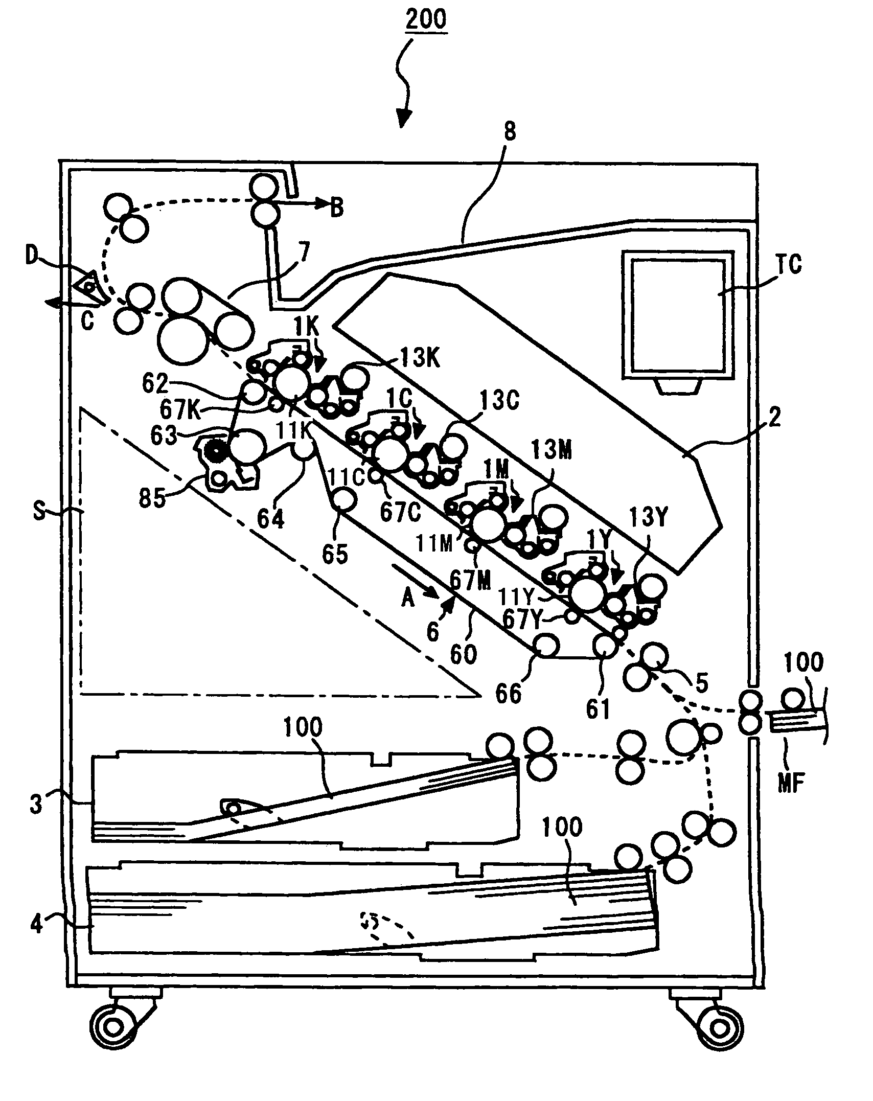
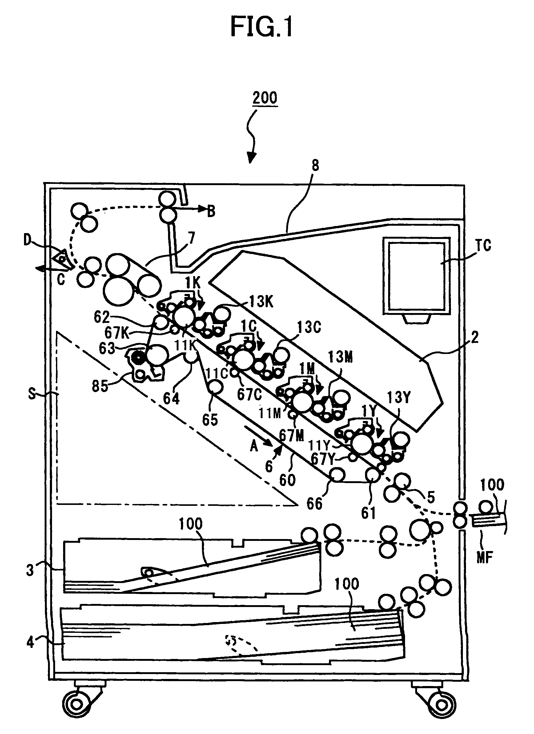
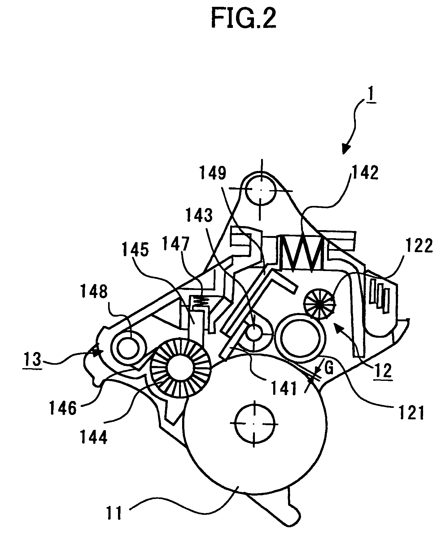
[0047]FIG. 1 is a schematic diagram showing a configuration of an imaging apparatus 200 according to an embodiment of the present invention. FIG. 2 is a schematic diagram showing a configuration of an image forming unit 1 of the imaging apparatus 200 shown in FIG. 1. The imaging apparatus 200 includes four image forming units 1Y, 1M, 1C, and 1K for forming images in colors yellow (Y), magenta (M), cyan (C), and black (K). The image forming units 1Y, 1M, 1C, and 1K respectively include image carriers 11Y, 11M, 11C, and 11K, charge units 12Y, 12M, 12C, and 12K, developing units 13Y, 13M, 13C, and 13K, and cleaning units 14Y, 14M, 14C, and 14K. The image forming units 1Y, 1M, 1C, and 1K are-positioned so that the rotational axes of their respective image carriers 11Y, 11M, 11C, and 11K may be parallel, and the image forming units 1Y, 1M, 1C, and 1K are aligne...


PUM

PropertyMeasurementUnit
Lengthaaaaaaaaaa
Forceaaaaaaaaaa
Distanceaaaaaaaaaa

Abstract

An imaging apparatus that is capable of realizing good cleaning characteristics and transfer characteristics, and obtaining a high quality image using toner having a high average roundness is provided. The imaging apparatus includes an image carrier, a charge unit, a developing unit, a transfer unit, and a cleaning unit. The transfer unit may directly transfer a toner image onto a recording medium that is carried by a transfer belt, or transfer the toner image onto the transfer belt first to then transfer the toner image onto the recording medium from the transfer belt. The cleaning unit includes a cleaning blade and a brush roller. The toner used in the imaging apparatus has an average roundness Ψ within a range of 0.93˜0.99, and a friction coefficient μs of the image carrier satisfies a condition, friction coefficient μs≦3.6−3.3×average roundness Ψ.

Description

BACKGROUND OF THE INVENTION[0001]1. Field of the Invention[0002]The present invention relates to an electrophotographic imaging apparatus such as a copying machine, a laser beam printer, and a facsimile machine, and a process cartridge and toner that are used in the electrophotographic imaging apparatus.[0003]2. Description of the Related Art[0004]Conventionally, in the field of electrophotographic imaging apparatuses such as copying machines, laser beam printers, and facsimile machines, an imaging technique of forming a latent image by charging a surface of a photoconductor corresponding to an image carrier is known.[0005]Currently, a technique is being developed for decreasing the particle diameter and increasing the roundness of toner used in an imaging apparatus in order to improve the output image quality. In such case, there is a limit to decreasing the particle diameter and increasing the roundness of the toner produced by a conventional pulverization method. Thereby, toner p...

Claims


Application Information

Patent Timeline
IPC IPC(8): G03G15/00G03G9/08G03G5/04G03G5/05G03G5/147G03G9/087G03G9/097G03G15/02G03G15/08G03G21/00G03G21/10
CPCG03G5/0507G03G5/14704G03G5/14713G03G9/0819G03G9/0827G03G9/08755G03G21/0029G03G9/08768G03G9/08793G03G9/09708G03G9/09725G03G21/0035G03G9/08764
Inventor KOIKE, TOSHIOMURAKAMI, EISAKUYANAGIDA, MASATOSHINTANI, TAKESHIKUMAGAI, NAOHIROSAMPE, ATSUSHITOMITA, MASAMINAGASHIMA, HIROYUKIKAWASUMI, MASANORIUCHITANI, TAKESHI
Owner RICOH KK
Learn More