
Method and device for filtering a signal

a signal filtering and signal technology, applied in the direction of adaptive control, electric control, instruments, etc., can solve the problems of generating a lag error and the effect of reducing the drive torqu

Inactive Publication Date: 2006-05-23
ROBERT BOSCH GMBH
View PDF16 Cites 38 Cited by
  • Summary
  • Abstract
  • Description
  • Claims
  • Application Information

AI Technical Summary

Benefits of technology

[0003]According to an exemplary embodiment and / or exemplary method of the present invention, respective lag errors may be compensated for without limitations of the filtering effect having to be accepted, particularly in the case of stepwise changes in the input variable.

Problems solved by technology

Such filtering for the damping of the activation of systems may, in response to ramp-like changes in the input variable, generate a lag error.
In an internal combustion engine application, for example, this may have the effect of a diminished drive torque.

Method used


Image

  • Method and device for filtering a signal
  • Method and device for filtering a signal
  • Method and device for filtering a signal

Examples


Embodiment Construction

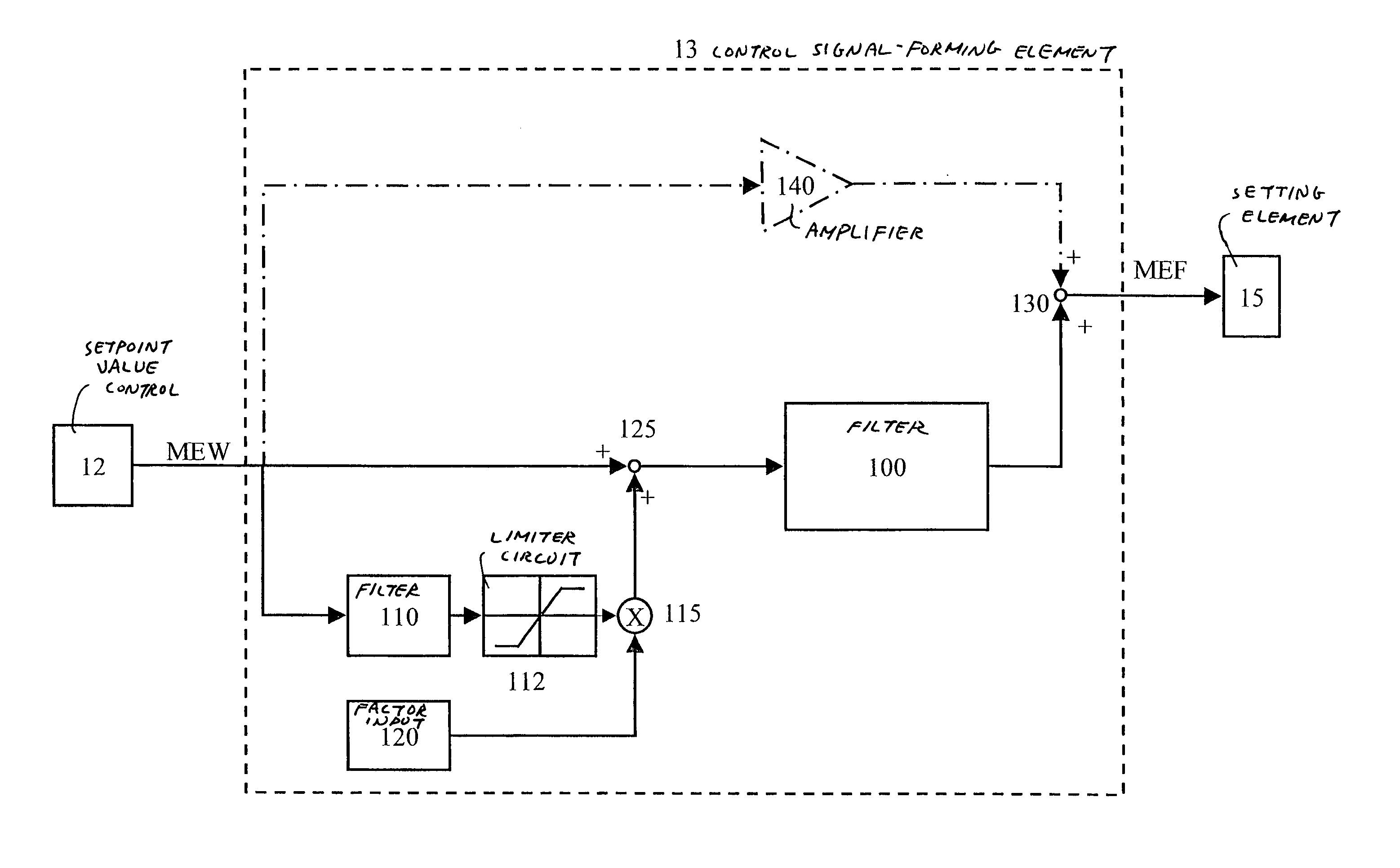
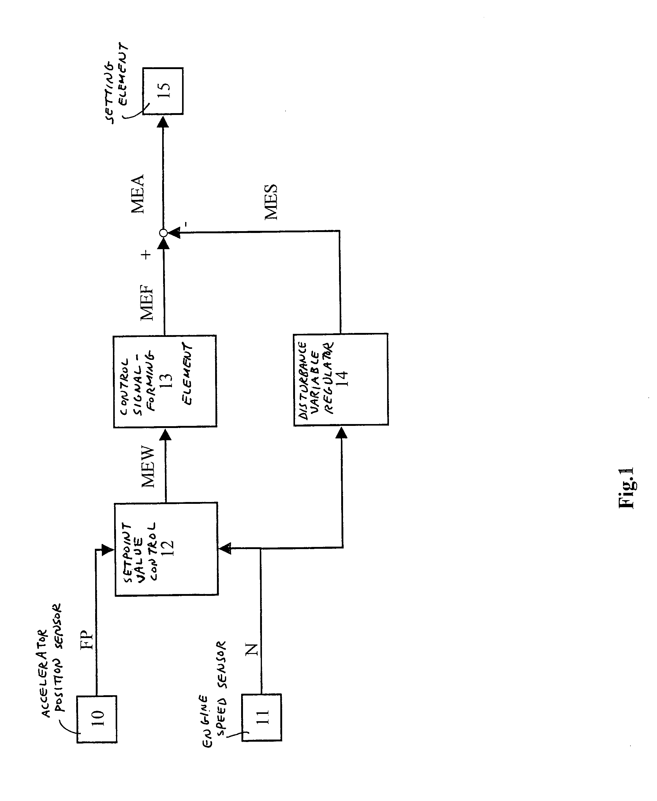
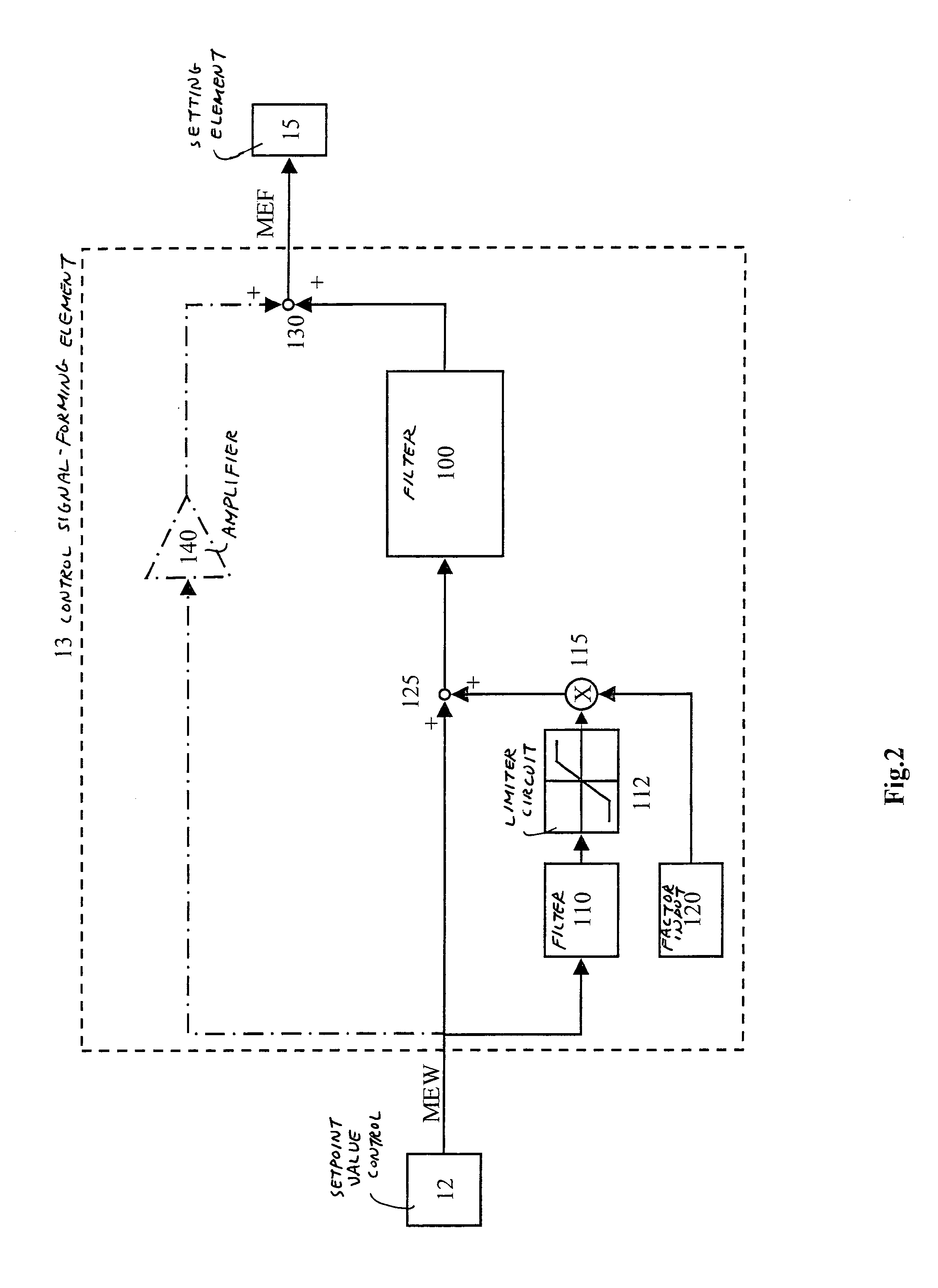
[0006]The present invention is described below, using the example of a fuel quantity signal in a self-igniting internal combustion engine. However, the present invention is not limited to this application. It may also be used in the case of other signals, such as, for example, in the case of signals which are used for the control of internal combustion engines. In particular, the exemplary method may be suitable for signals which influence or characterize the output torque. Such signals may be, for example, a fuel quantity signal, signals controlling power-influencing actuators, a quantity input signal, the output signal of an accelerator pedal sensor or a engine speed signal.

[0007]FIG. 1 shows a fundamental construction of a fuel metering system of an internal combustion system. Number 10 denotes an accelerator position sensor and 11 denotes a speed sensor. A setpoint value control 12 is connected to the accelerator-pedal position sensor and speed sensor 11. Output signal MEW of th...


PUM


Abstract

A method and a device are described for filtering a variable. A first filtering arrangement is used for forming an output variable as a function of an input variable, the first filtering arrangement having at least a delaying effect. The input variable of the first filtering arrangement is corrected using a correcting variable which is obtained by starting from the input variable of the first filtering arrangement and by filtering, using a second filtering arrangement.

Description

FIELD OF THE INVENTION[0001]The present invention relates to a method and a device for filtering a signal.BACKGROUND INFORMATION[0002]A method and a device for filtering a signal are referred to, for example, in the German Published Patent Application No. 195 37 787. A driver input amount may be filtered using a control signal-forming element. The filtering may be configured so that, for example, rapid driver input quantity changes (pedal force) may not act undamped on the fuel metering, and thus initiation of longitudinal vibrations of the vehicle may be avoided. Such filtering for the damping of the activation of systems may, in response to ramp-like changes in the input variable, generate a lag error. Therefore, the output variable may follow the input variable only at a delay. In an internal combustion engine application, for example, this may have the effect of a diminished drive torque.SUMMARY OF THE INVENTION[0003]According to an exemplary embodiment and / or exemplary method o...

Claims


Application Information

Patent Timeline
Patent Type & Authority Patents(United States)
IPC IPC(8): G06F17/10F02D11/10F02D45/00F02D41/06F02D41/40
CPCF02D11/105F02D2011/103F02D11/10
Inventor WAGNER, HORSTSAMUELSEN, DIRKFEHRMANN, RUEDIGER
Owner ROBERT BOSCH GMBH
Learn More