
Adjustable pressure regulator

a pressure regulator and adjustable technology, applied in fluid pressure control, process and machine control, instruments, etc., can solve problems such as the replacement of seals to achieve adjustment, and achieve the effect of increasing the regulated outlet pressur

Inactive Publication Date: 2006-05-30
UNIVERSITE CATHOLIQUE DE LOUVAIN +1
View PDF13 Cites 11 Cited by
  • Summary
  • Abstract
  • Description
  • Claims
  • Application Information

AI Technical Summary

Benefits of technology

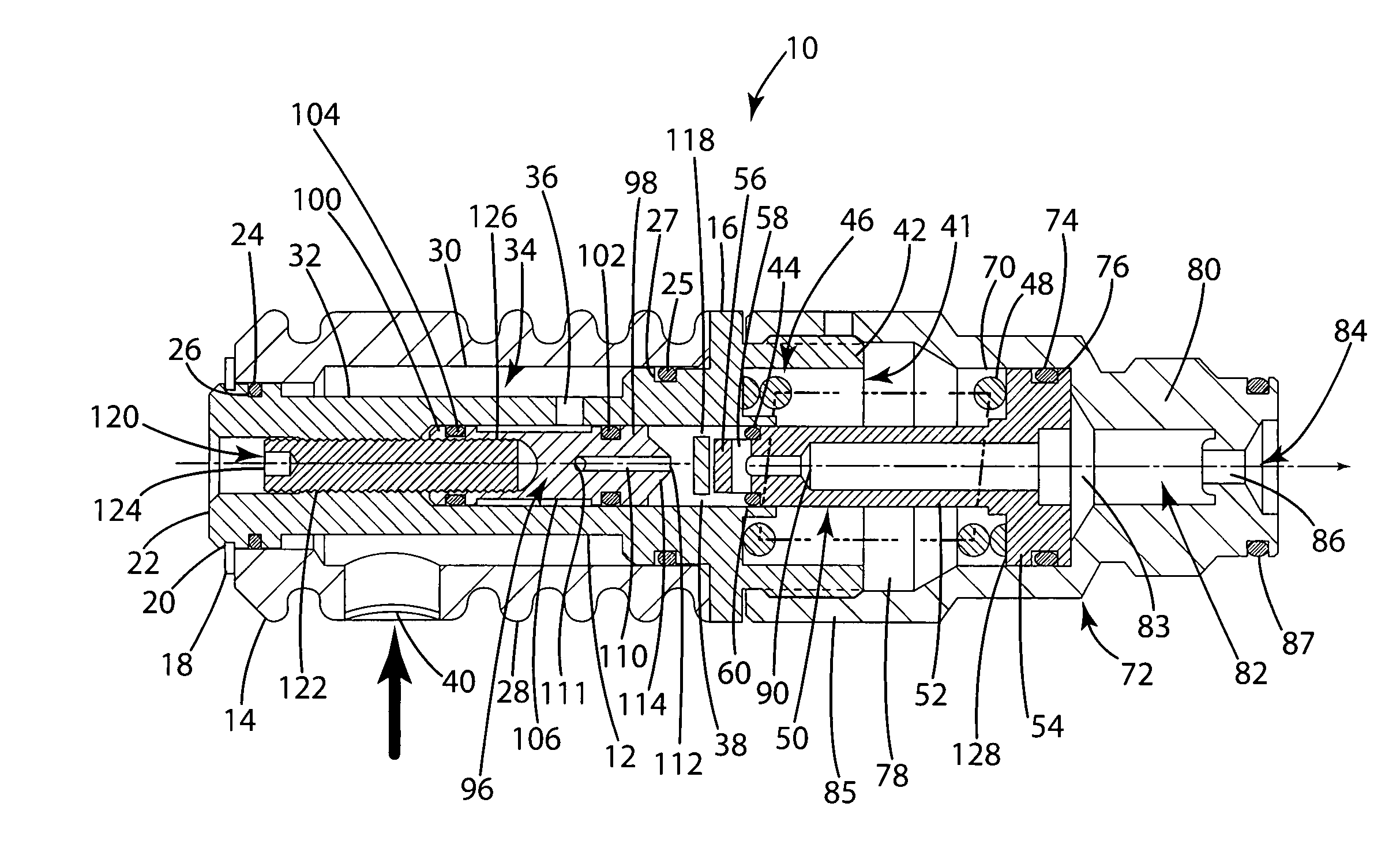
The present invention is an improvement to a floating seal piston type pressure regulator valve. It includes a valve seat that can be adjusted to change the regulated outlet pressure. The valve seat is connected to a separate member that can be moved in the valve chamber. The valve body also has an expansion chamber that helps to precharge the pressure regulator and reduce recycle time. The expansion chamber housing has ribs on its outer surface to enhance heat transfer. These features improve the performance and efficiency of the pressure regulator valve.

Problems solved by technology

Replacement of seals to achieve adjustment, however, can be inconvenient.

Method used


Image

  • Adjustable pressure regulator
  • Adjustable pressure regulator

Examples


Embodiment Construction

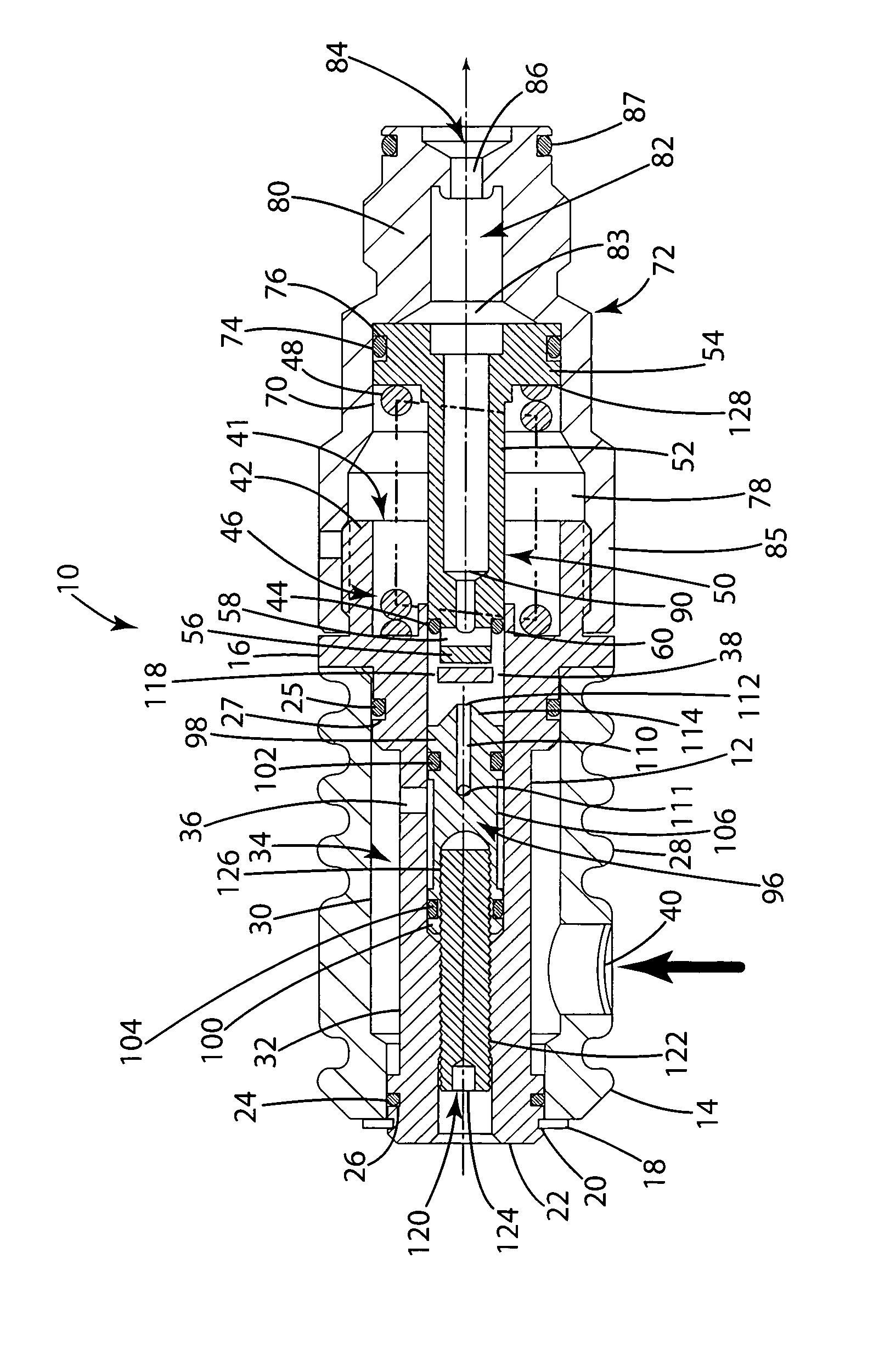
[0013]Referring to the drawings, pressure regulator 10 includes regulator body 12 mounted in expansion chamber housing 14 that surrounds the body on one side of an outwardly extending radial flange 16. An external retaining ring 18 fits in a groove 20 in end 22 of regulator body 12 and holds the expansion chamber housing 14 on the body between the retaining ring and flange 16. A lower housing seal 24 that fits in a groove 26 adjacent rear end 22 of the regulator body housing is positioned between regulator body 12 and expansion chamber housing 14 and restrains pressure leakage through the end of the expansion chamber housing. An upper housing seal 25 at the other end of the body 12 fits in groove 27 and prevents fluid leakage from the other end of the expansion chamber housing. Regulator body 12 can have a ribbed outer surface 28 that serves as a hand grip and provides increased external surface for thermal transfer.

[0014]Expansion chamber housing 14 has a cylindrical interior surfa...


PUM


Abstract

An adjustable floating seal piston type pressure regulator valve of the type wherein a spring biased piston engages a floating seal in a regulator body valve chamber to open and close a valve seat outlet in the valve chamber. The valve seat comprises a separate member from the regulator body and is adjustably movable in the valve chamber toward and away from the piston, such that movement of the valve seat toward the piston serves to lower a regulated outlet pressure and movement of the valve seat away from the piston serves to increase the regulated outlet pressure. The valve seat member is moved by an adjustment screw that is externally accessible by an adjustment tool. A tubular expansion chamber surrounds the regulator body and provides an enlarged expansion chamber that reduces valve recycle time. Convolutions or ribs in the expansion chamber housing enhance heat through transfer to the valve gases.

Description

BACKGROUND OF THE INVENTION[0001]The present invention relates to fluid flow pressure regulators and more particularly to an easily adjustable secondary pressure regulator having an expansion chamber that improves recycle time.[0002]Fluid flow pressure regulators are used for a number of purposes. Pressure regulators include primary pressure regulators and secondary pressure regulators. These can be used for a number of gases, including carbon dioxide (CO2). One such use for such pressure regulators is for gas-powered weapons, such as paintball guns. A primary regulator typically is not adjustable and reduces line pressure from about 3500 or 4800 psi to 500–800 psi. A secondary regulator may be adjustable and reduces pressure from 500–800 psi to any one of a number of operating ranges, such as 150–250 psi, 250–350 psi, and 350–450 psi. A different model of secondary pressure regulator may be used for each secondary pressure range.[0003]Adjustable pressure regulators are known. An ad...

Claims


Application Information

Patent Timeline
Patent Type & Authority Patents(United States)
IPC IPC(8): G05D16/02G05D16/10
CPCG05D16/103Y10T137/6525Y10T137/7808
Inventor ZUCK, JAMES C.
Owner UNIVERSITE CATHOLIQUE DE LOUVAIN
Learn More