Vapor-liquid separating type heat pipe device

a heat pipe device and vapor liquid technology, applied in the direction of insulated conductors, semiconductor/solid-state device details, cables, etc., can solve the problems of dryout phenomenon that can occur in the conventional heat pipe device, and achieve the effect of quickly dissipating hea

Inactive Publication Date: 2006-05-30
LUO CHIN KUANG
View PDF21 Cites 59 Cited by
  • Summary
  • Abstract
  • Description
  • Claims
  • Application Information

AI Technical Summary

Benefits of technology

[0012]Therefore, the object of the present invention is to provide a vapor-liquid separating type heat pipe device that can dissipate heat quickly and that is capable of overcoming the aforementioned drawbacks of the prior art.

Problems solved by technology

This entails entrainment problem between vapor and liquid.
Moreover, when the heat flux is excessive, a dryout phenomenon can occur in the conventional heat pipe device.

Method used


Image

  • Vapor-liquid separating type heat pipe device
  • Vapor-liquid separating type heat pipe device
  • Vapor-liquid separating type heat pipe device

Examples


Embodiment Construction

[0026]Before the present invention is described in greater detail, it should be noted that like elements are denoted by the same reference numerals throughout the disclosure.

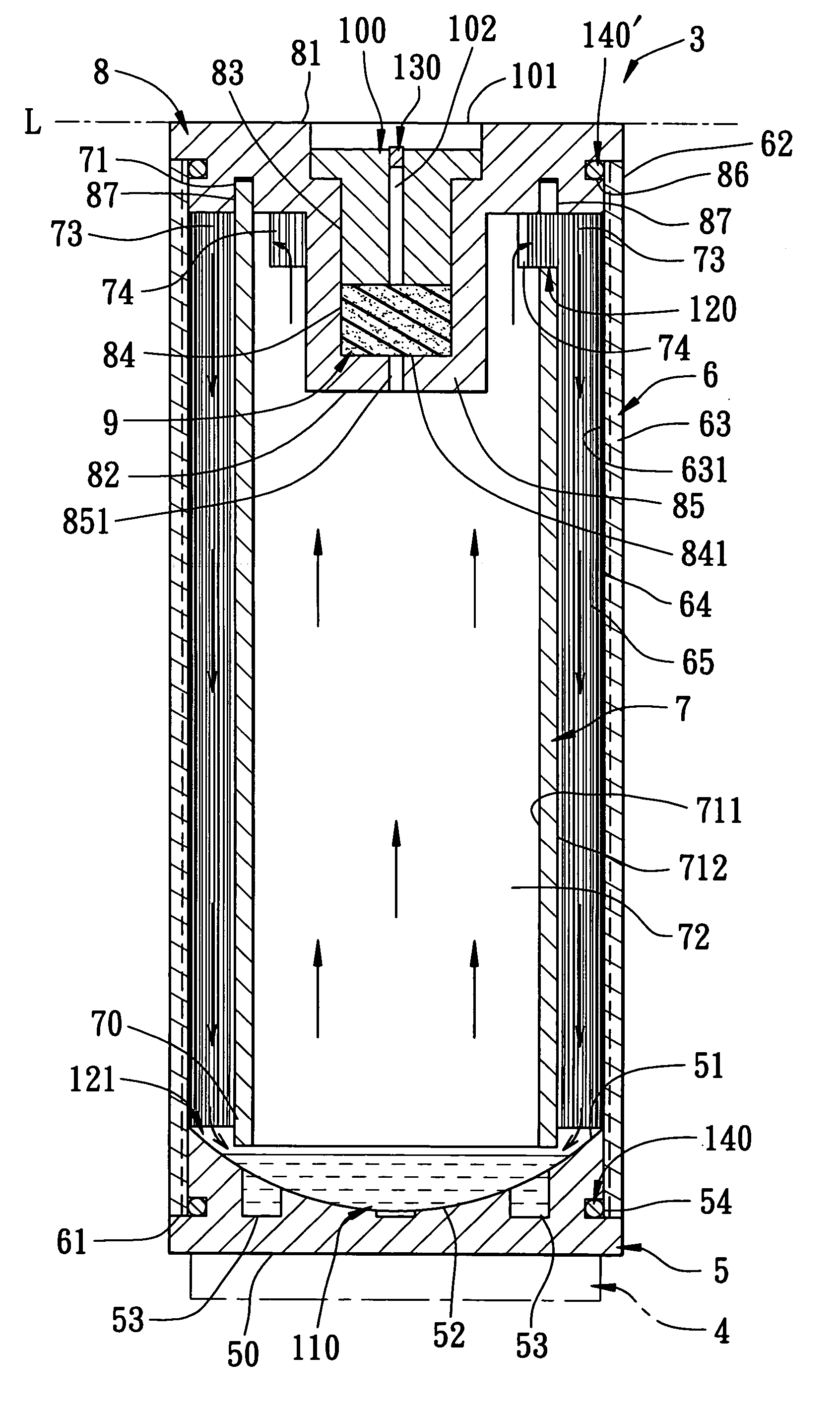
[0027]Referring to FIGS. 4, 5 and 6, the first preferred embodiment of a vapor-liquid separating type heat pipe device 3 according to the present invention is shown to comprise a heat sink member 5, a tubular outer body 6, a tubular inner body 7, a cover member 8, a top vapor passage 120, a bottom liquid passage 121, an elastic sealing member 9, a securing member 100, and a heat transfer fluid 110.

[0028]The heat sink member 5 is adapted to be mounted on a heat source 4 (see FIG. 5), such as a central processing unit, and is made of a good heat conductive material, such as aluminum, copper or a metal alloy. The heat sink member 5 has a bottom face 50 (see FIG. 5) adapted to be in contact with the heat source 4, and a top face 51 opposite to the bottom face 50 and indented downwardly to define a fluid accumulating...


PUM


Abstract

A vapor-liquid separating type heat pipe device includes a heat sink member mountable on a heat source, tubular outer and inner bodies, a heat transfer fluid, a top vapor passage, and a bottom liquid passage. The outer body has an outer peripheral wall defining an inner chamber. The inner body is disposed in the inner chamber, and has an inner peripheral wall defining thereinside an evaporating space and cooperating with the outer peripheral wall to define a condensing space therebetween. The fluid is introduced into the inner chamber. The vapor passage is provided between and is in fluid communication with the evaporating and condensing spaces. The liquid passage is provided between and is in fluid communication with the condensing space and the heat sink member. The vapor and liquid passages are located proximate to the top and bottom ends of the inner and outer bodies, respectively.

Description

CROSS-REFERENCE TO RELATED APPLICATION[0001]This application claims priority of Taiwanese Application No. 092119854, filed on Jul. 21, 2003.BACKGROUND OF THE INVENTION[0002]1. Field of the Invention[0003]The invention relates to a heat pipe device, more particularly to a vapor-liquid separating type heat pipe device that can dissipate heat quickly.[0004]2. Description of the Related Art[0005]Referring to FIGS. 1 to 3, a conventional heat pipe device includes an outer body 1, an inner body 2, and a heat transfer fluid 300.[0006]The outer body 1 has an open end 11, and an outer wall 12 defining a first receiving space 13. An inner wall surface of the outer wall 12 is formed with a capillary structure 14. The capillary structure 14 includes a plurality of spaced-apart protruding pieces 141 formed and distributed evenly on the inner wall surface of the outer wall 12.[0007]The inner body 2 is disposed in the outer body 1, and has an inner wall 21 defining a second receiving space 22. The...

Claims


Application Information

Patent Timeline
Patent Type & Authority Patents(United States)
IPC IPC(8): F28D15/00F28D15/02F28D15/04
CPCF28D15/0233F28D15/04F28D15/0283
Inventor LUO, CHIN-KUANG
Owner LUO CHIN KUANG
Why Eureka
Try Eureka