Control valve

a control valve and valve body technology, applied in the direction of diaphragm valves, engine diaphragms, caps, etc., can solve the problems of low responsiveness, high cost, and difficulty in fine adjustment, and achieve the effect of improving the responsiveness of the control circui

Inactive Publication Date: 2006-05-30
MKS JAPAN INC
View PDF5 Cites 9 Cited by
  • Summary
  • Abstract
  • Description
  • Claims
  • Application Information

AI Technical Summary

Benefits of technology

[0005]To achieve the stated object, in the present invention, an actuator operated by a solenoid and a force amplifying means utilizing hydraulic pressure are used in combination with a diaphragm, to thereby provide a diaphragm valve made of a fluoropolymer such as Teflon™, and which is compact in size, has low power consumption, and which is capable of exerting a large force.
[0009]To enable effective control of a flow rate of a chemical liquid, it is required to use a diaphragm made of Teflon™. However, a Teflon™ diaphragm is relatively hard. Therefore, a large force must be employed to displace such a diaphragm. Further, since the diaphragm is directly subject to a fluid under high pressure, it is necessary to employ a large operating force so as to counteract this fluid pressure. In the control valve of the present invention in which a force amplifying means is provided, the valve can be operated by amplifying a relatively low force of the plunger. Accordingly, it is made possible to obtain a high-force diaphragm valve while utilizing a simple and conventional valve structure. Thus, the control valve of the present invention is inexpensive since it has a simple structure. Further, fine adjustments can be conducted without any risk of gear backlash. In addition, the control valve of the present invention has high responsiveness and requires use of only a relatively simple control circuit.

Problems solved by technology

However, use of a linear actuator of this type gives rise to various problems, such as high cost, difficulty in making fine adjustments due to gear backlash, low responsiveness, complexity of a control circuit, and so on.

Method used


Image

  • Control valve
  • Control valve
  • Control valve

Examples


Embodiment Construction

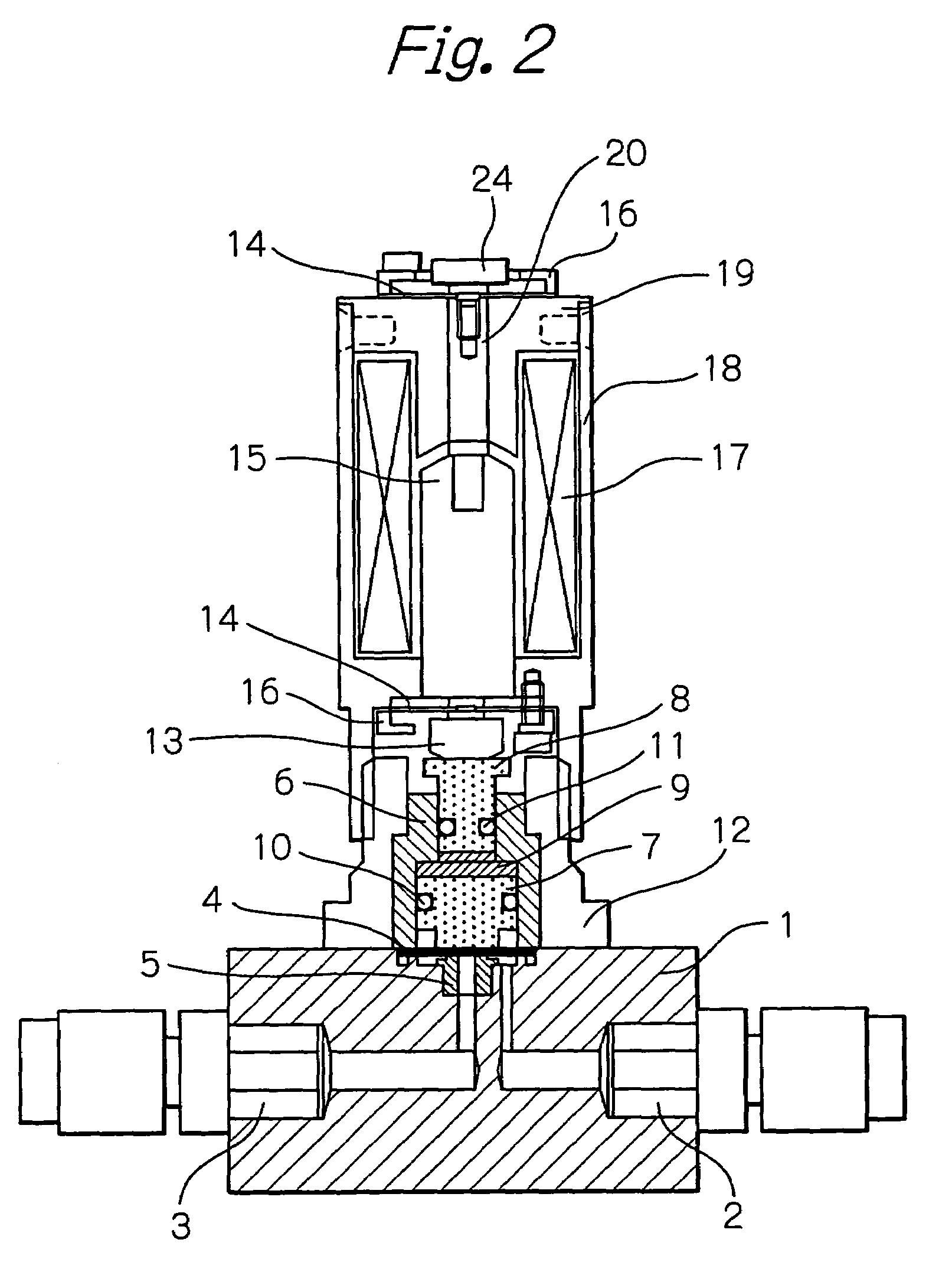
[0019]FIG. 2 shows an entire construction of a control valve for controlling a flow rate of a fluid according to an embodiment of the present invention, in which the valve is open when the solenoid is energized.

[0020]In the control valve shown in FIG. 2, a base 1 is made of a fluoropolymer such as Teflon™. The base 1 includes an inlet 2 and an outlet 3 for a fluid, and a fluid flow path extending from the inlet 2 to the outlet 3. An orifice is formed in a part of the fluid flow path. A valve seat 5 is provided in the orifice. A diaphragm 4 made of a fluoropolymer such as Teflon™ is disposed so as to close an opening of the valve seat 5. The diaphragm 4 acts as a valve head and, together with the valve seat 5, forms a fluid flow rate control valve. That is, the diaphragm 4 is displaced by a controlled amount, so as to form, between the diaphragm 4 and the valve seat 5, a fluid flow path corresponding to the amount of displacement, to thereby allow a fluid to flow at a desired rate th...


PUM


Abstract

An actuator operated by a solenoid and a force amplifying means utilizing hydraulic pressure are used in combination with a diaphragm, to thereby provide a diaphragm valve made of Teflon™, and which is compact in size, has low power consumption, and which is capable of exerting a large force. The force amplifying means mainly comprises a cylinder including cylinder portions having different cross-sectional areas and oil filled in the cylinder. A force amplification ratio is equal to a ratio between the cross-sectional areas of the cylinder portions. A plunger which receives a biasing force of a spring is provided on an upper side of the force amplifying means. The plunger is operated by a solenoid, and a driving force of the plunger is amplified by the force amplifying means and transmitted to the diaphragm, thus adjusting a degree of valve opening. A flow rate control valve of the present invention is free from the problems of conventional control valves, and used for controlling a flow rate of a fluid, such as a chemical liquid or an exceptionally high-purity liquid.

Description

BACKGROUND OF THE INVENTION[0001]The present invention relates to a proportional control valve capable of controlling a flow rate of a fluid to be at a desired level.[0002]As a control valve for controlling a flow rate of a chemical liquid or an exceptionally high-purity liquid, it is preferable to use a valve made of Teflon™ so as to prevent entry of metal ions into the liquid. Further, to enable a flow rate of a chemical liquid to be precisely controlled, a diaphragm type valve is preferably used in which a degree of valve opening can be controlled as desired. A diaphragm made of Teflon™ is directly subject to a fluid pressure, and it is necessary to impart by way of an actuator a force that is sufficiently high to counteract this fluid pressure. Generally, as an actuator in this field of application, a linear actuator comprising a precision gear and a stepping motor is used (reference is made to, for example, U.S. Pat. No. 6,145,538).[0003]However, use of a linear actuator of thi...

Claims


Application Information

Patent Timeline
Patent Type & Authority Patents(United States)
IPC IPC(8): F16K31/02F16K7/16F16K7/14F16K31/06
CPCF16K7/14F16K31/1225F16K31/06
Inventor SUZUKI, ISAO
Owner MKS JAPAN INC
Why Eureka
Try Eureka