Method and apparatus for a scissors ergonomic support

a scissors and ergonomic technology, applied in the field of ergonomic supports, can solve the problems of large number of turns required on a manual hand crank or lever, less comfort, and shrinkage of the surface area contacting the passenger, and achieve the effects of reducing bulk and number of components, and being convenient to us

Inactive Publication Date: 2006-05-30
L & P PROPERTY MANAGEMENT CO
View PDF141 Cites 59 Cited by
  • Summary
  • Abstract
  • Description
  • Claims
  • Application Information

AI Technical Summary

Benefits of technology

[0017]The present invention supports the lumbar spine with pressure surfaces that are generally vertical and located bilaterally adjacent to the vertebra of the spine. The centrally located, vertical hinge creates a channel for relief of pressure on the spinal vertebrae.
[0018]The present invention makes the combination of components within a seat more compact, especially with regard to eliminating the bulk and number of components required. It uses a relatively small number of moving parts which are simple in design and movement. The present invention streamlines the manufacture, assembly, packaging and shipping of the device and of seats incorporating the device, lowers production costs and increases the durability and useable life of the device and seats incorporating it. The scissors ergonomic support may be mounted in any of a variety of seat frames and suspension systems.
[0019]The scissors lumbar support of the present invention creates an increased ratio of pressure surface travel towards a passenger in relation to the travel required of an actuator linkage, such as a Bowden cable. The pressure surfaces of the scissors lumbar support move out relative to the pivot upon actuation. Also, the pivot itself moves out an additional amount relative to the seat frame because the scissors l...

Problems solved by technology

A large number of turns required on a manual hand-crank or lever are undesirable.
In addition to the load created by the weight of the passenger, these prior art lumbar devices have to overcome the load of flexing the pressure surface, and overcome the friction inherent in sliding the moving ends of such arching lumbar supports along their stationary mounts.
Another disadvantage of arching lu...

Method used


Image

  • Method and apparatus for a scissors ergonomic support
  • Method and apparatus for a scissors ergonomic support
  • Method and apparatus for a scissors ergonomic support

Examples


Embodiment Construction

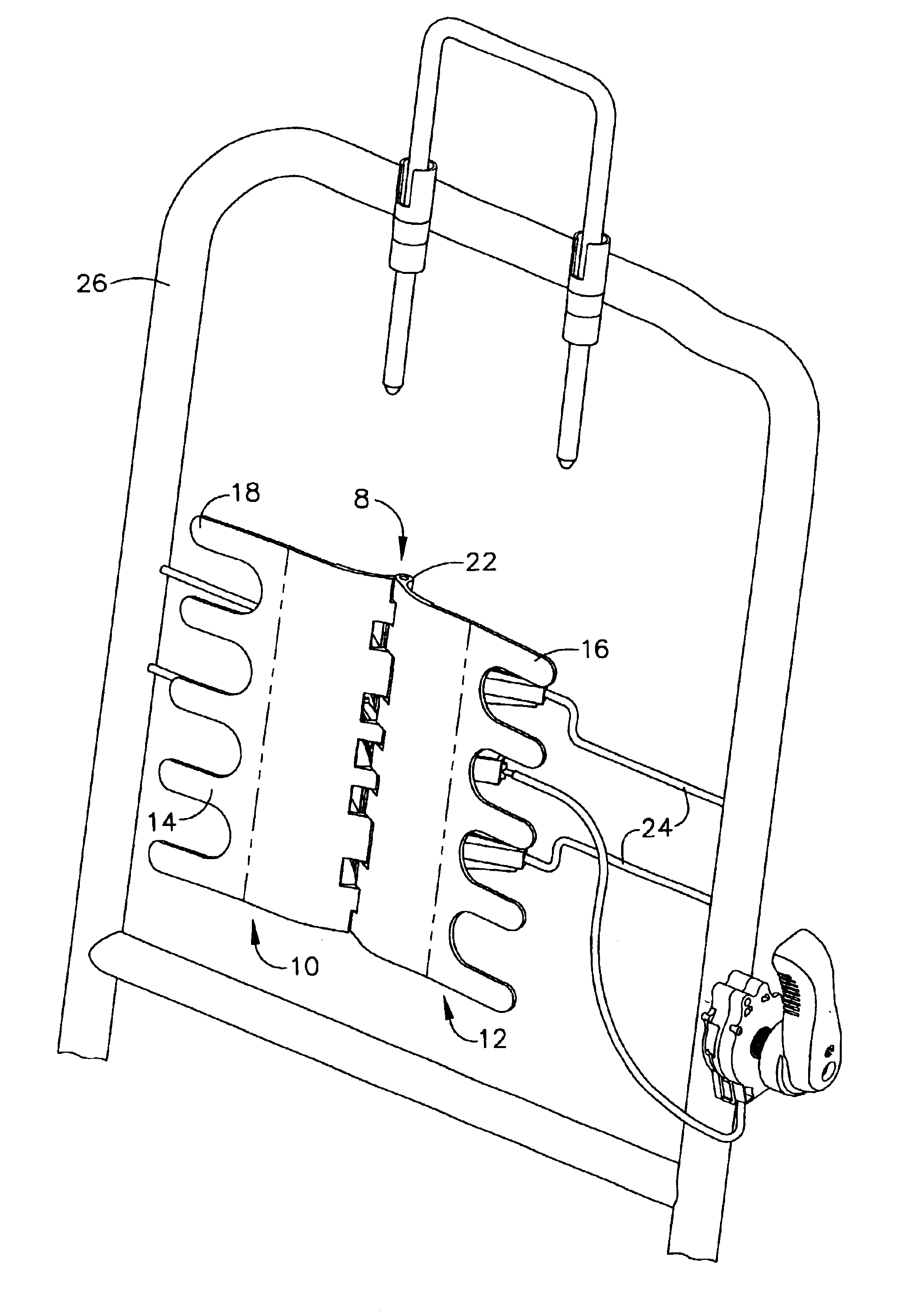
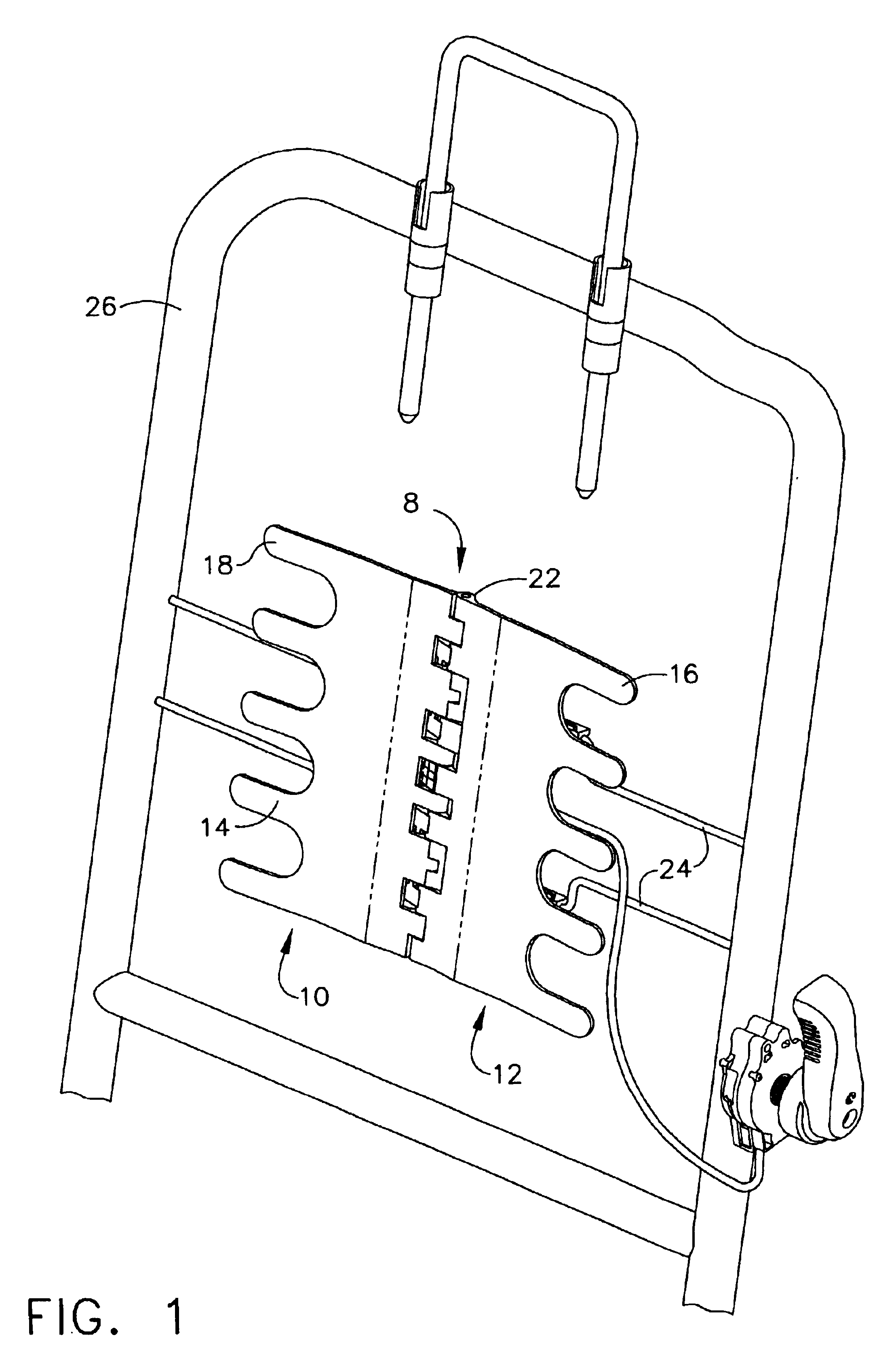
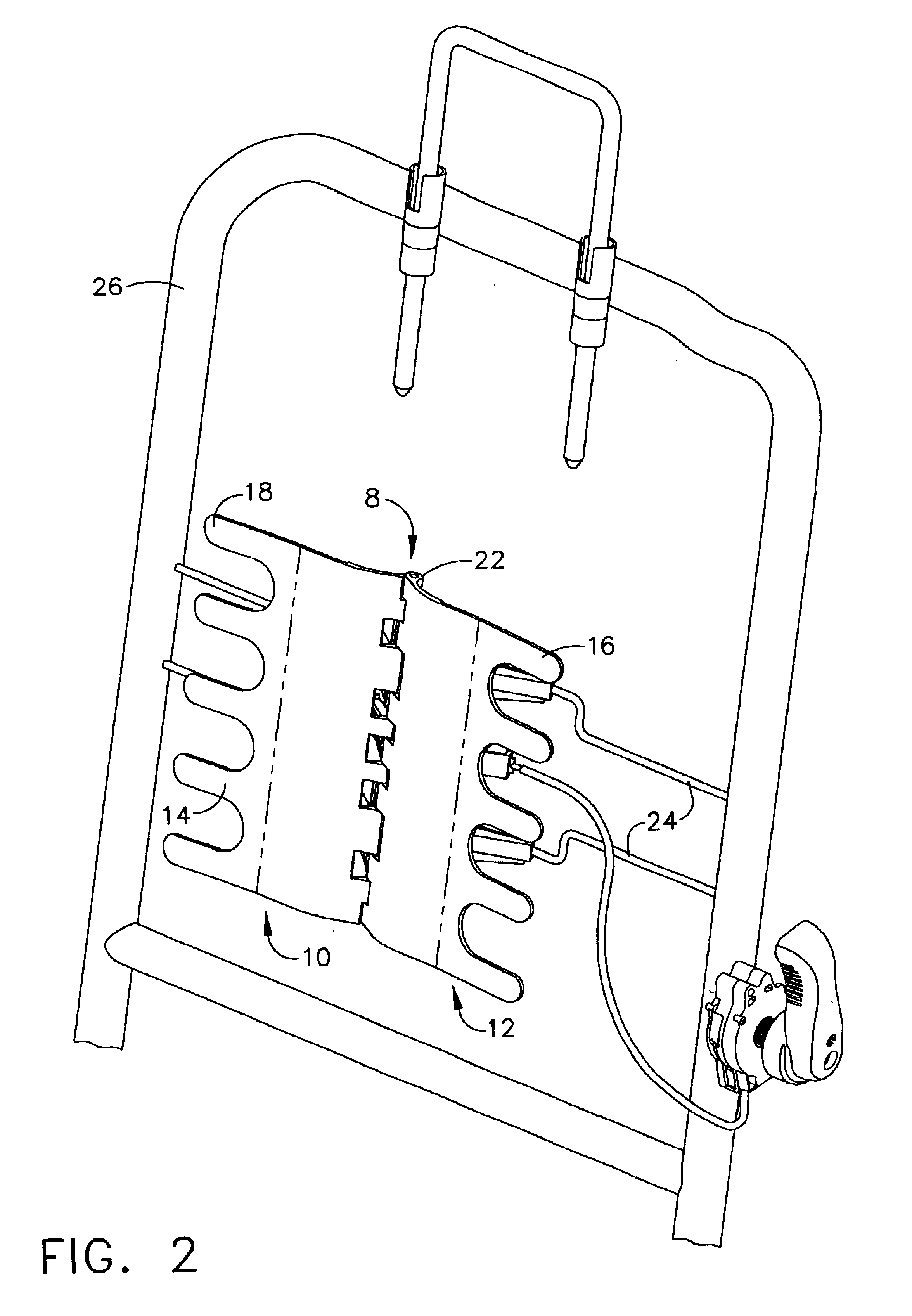
[0041]Referring to the accompanying drawings in which like reference numbers indicate like elements, FIGS. 1 and 2 are front views of the first embodiment of the scissors lumbar support of the present invention. FIGS. 3 and 4 are back views of the first embodiment and FIGS. 5 and 6 are top views of the first embodiment.

[0042]Referring now to FIGS. 1 and 2, the present invention is comprised of two hinging arms, 10 and 12, connected at a vertical hinge, 8. These arms are preferably molded plastic but may be metal. They are deployed in a left handed and right handed fashion. They may be manufactured in left and right handed versions, but preferably are manufactured to be symmetrical. In assembly, in order to create a bilateral hinge support from symmetrical arms, one of the arms is simply inverted to create the mirror image of the other.

[0043]Each arm has three portions. A forward extending aspect, 14 and 16, is the lumbar supporting pressure surface or pad. Although the configuration...


PUM


Abstract

A scissors lumbar support includes a hinge axle and two arms each having a forward portion and a rearward portion. The forward portions are lumbar support pads. At least one of the rearward portions of the arms are adapted to operatively engage a force applicator. Each of the arms hinge around a hinge axle upon application of force by a force applicator. At least one of the rearward portions of the arms are mountable on a seat frame.

Description

CROSS-REFERENCE TO RELATED APPLICATIONS[0001]None.STATEMENT REGARDING FEDERALLY SPONSORED RESEARCH OR DEVELOPMENT[0002]Not applicable.BACKGROUND OF THE INVENTION[0003]1. Field of the Invention[0004]This invention relates to ergonomic supports, especially lumbar supports, for seats, particularly for automobile seats.[0005]2. Related Art[0006]Modern seat designs commonly include lumbar supports for the comfort of the person sitting in the seat. In fact, it is becoming more common for seats to incorporate a variety of components for passenger comfort, including heating and cooling ducts and the like. The promulgation of components within the confines of a seat creates a need for smaller, more compact components. Saving space is also served by reducing the number of components required to provide ergonomic support.[0007]It is desirable in designing ergonomic controls for automobile seats to minimize the amount of manual effort a passenger needs to exert to move an ergonomic device such ...

Claims


Application Information

Patent Timeline
IPC IPC(8): A47C3/025B60N2/66
CPCB60N2/66B60N2/6673B60N2/6671B60N2/20
Inventor MCMILLEN, ROBERT
Owner L & P PROPERTY MANAGEMENT CO
Why Eureka
Try Eureka