Magnetometer having a dynamically adjustable bias setting and electronic vehicle compass incorporating the same

a dynamically adjustable, magnetometer technology, applied in the field of magnetometers, can solve the problems of automobiles affecting the external magnetic field, and affecting the accuracy of magnetic measurements

Inactive Publication Date: 2006-05-30
GENTEX CORP
View PDF79 Cites 24 Cited by
  • Summary
  • Abstract
  • Description
  • Claims
  • Application Information

AI Technical Summary

Benefits of technology

[0010]According to one embodiment of the present invention, a magnetometer is provided that comprises a sensor for sensing a magnetic field, a biasing circuit, and a processor. The sensor generates an output signal having a signal characteristic that varies in response to the sensed magnetic field and in response to an applied bias. The biasing circuit dynamically biases the sensor in response to a bias setting signal. The processor is coupled to receive the output signal from the sensor and coupled to the biasing circuit. The processor is operable to generate the bias setting signal and thereby control the biasing circuit to dynamically bias the sensor such that the signal characteristic of the output signal is maintained within a relatively small target range of levels. The processor determines the magnetic field component sensed by the sensor as a function of the bias setting applied to the sensor.

Problems solved by technology

A problem encountered in such magnetometers is that the core material characteristics vary with temperature and age.
One problem with providing an electronic compass in an automobile is that the automobile may distort the external magnetic field.
Further, as the vehicle travels past objects such as bridges, subways, power lines, railroad tracks, and other objects, these objects may cause disturbances in the magnetic field that are sensed by the electronic compass.
Such magnetic field disturbances may produce magnetic fields that cause the magnetic field sensed by the sensor coils to fall within a non-linear region of the inductance versus magnetic field strength curve.
Thus, the magnetometers of the above-described patents have limited ranges in which they can accurately detect the strength of the external magnetic field.

Method used


Image

  • Magnetometer having a dynamically adjustable bias setting and electronic vehicle compass incorporating the same
  • Magnetometer having a dynamically adjustable bias setting and electronic vehicle compass incorporating the same
  • Magnetometer having a dynamically adjustable bias setting and electronic vehicle compass incorporating the same

Examples


first embodiment

[0049]In a first embodiment, the field sensing inductive element is incorporated into a resonant circuit and driven at a nearly constant frequency by an AC drive signal which is superimposed or summed with the DC bias current setting. The AC drive signal is preferably of low enough amplitude to prevent the driving circuit for the coil from going into saturation. In the configuration, circuit resonance is preferably at or close to the detectable target state condition. A circuit is provided to measure the phase of the response of the resonant circuit relative to the driving signal. The phase of the response relative to the driving signal has a particular value which will be referred to as the target value when the inductance of the coil is at the value chosen as the detectable target state. The phase of the response relative to the driving signal may be converted to an analog signal and a low cost microcontroller with an 8-bit pulse-width modulated D to A converter for the biasing ci...

second embodiment

[0051]In a second embodiment, the resonant circuit is configured as a self resonating oscillator for which bias current may be set in much the same way as for the circuit with the phase measurement output and, in this case, the detectable target state is manifest by a particular response frequency or period and the continuous or multi-step indication (i.e., target range) is a deviation in frequency or period from the targeted frequency or period. Here, a frequency counter or pulse width timer may replace the A to D converter of the first example.

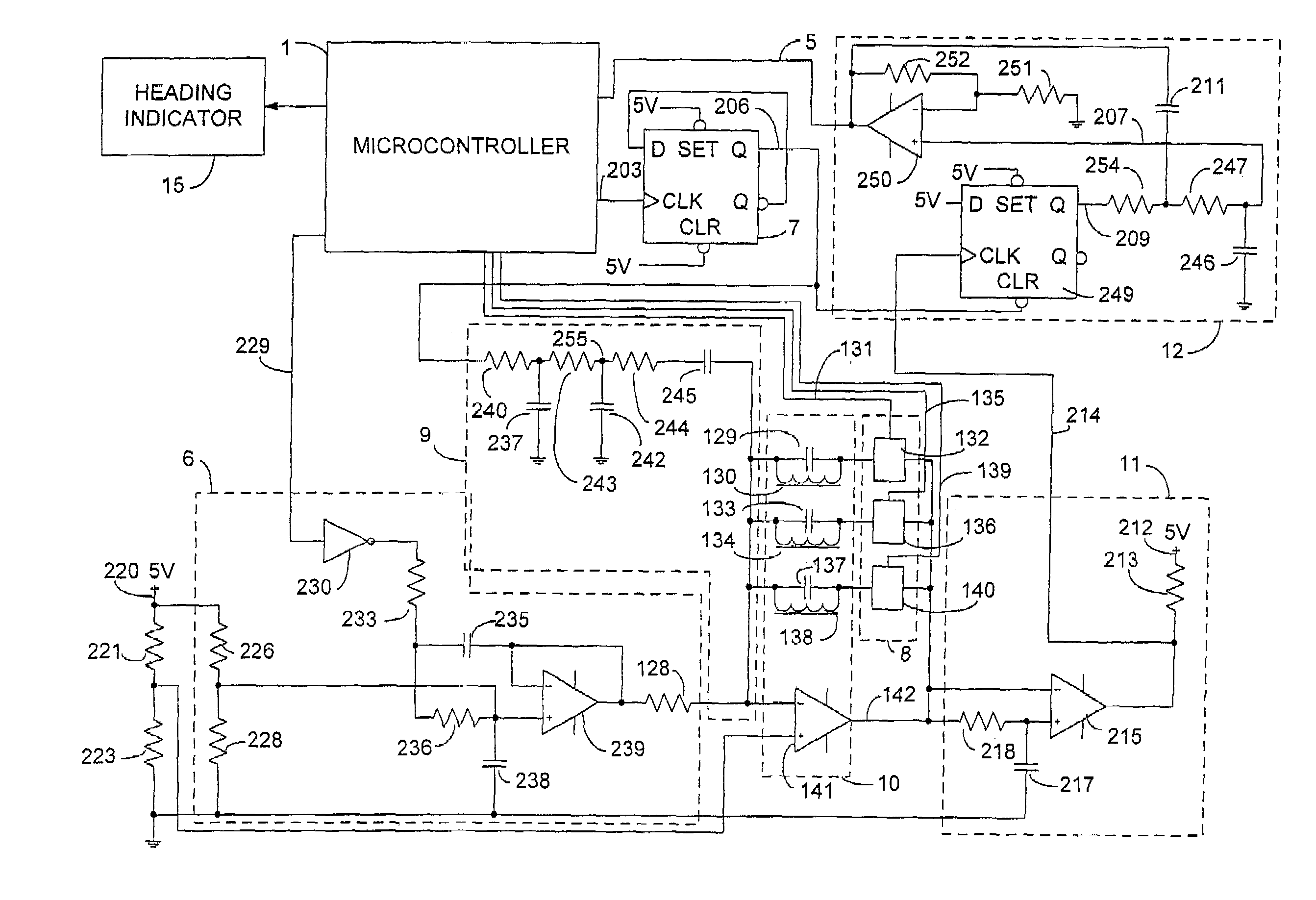
[0052]FIG. 3 is a block diagram of a magnetometer of the first embodiment of the present invention. This magnetometer is intended primarily for, but not limited to, reading the strength and direction of the Earth's magnetic field along with disturbing fields in a vehicle in order to determine and display the heading direction of the vehicle. The magnetometer includes a microcontroller 1, a biasing circuit 6, an input frequency source 7, a se...


PUM


Abstract

According to some embodiments of the present invention, a magnetometer includes at least one sensor for sensing a magnetic field component, a biasing circuit, and a processor. The sensor generates an output signal having a signal characteristic that varies in response to the sensed magnetic field component and in response to an applied bias. The biasing circuit dynamically biases the sensor in response to a bias setting signal. The processor is coupled to receive the output signal from the sensor and coupled to the biasing circuit. The processor is operable to generate the bias setting signal and thereby control the biasing circuit to dynamically bias the sensor such that the signal characteristic of the output signal is maintained in a target range. The processor determines the magnetic field component sensed by the sensor as a function of the bias setting applied to the sensor.

Description

CROSS-REFERENCE TO RELATED APPLICATIONS[0001]This application is a divisional of U.S. patent application Ser. No. 09 / 989,559, filed Nov. 20, 2001, now U.S. Pat. No. 6,653,831, the entire disclosure of which is incorporated herein by reference.BACKGROUND OF THE INVENTION[0002]The present invention generally relates to a magnetometer and more specifically relates to an electronic compass for use in a vehicle.[0003]Magnetometers are used in many different applications. One such application is an electronic compass for a vehicle. In such electronic compasses, magnetometers are utilized to ascertain the vehicle heading relative to the Earth's magnetic north pole. A typical electronic compass includes two magnetic field sensors both disposed with their axes lying in a horizontal plane with a first sensor having its axis aligned in parallel with the longitudinal axis of the vehicle and the second sensor having its axis disposed orthogonal to the axis of the first sensor. The sensors are th...

Claims


Application Information

Patent Timeline
Patent Type & Authority Patents(United States)
IPC IPC(8): G01R33/04G01C17/32G01C17/30G01R33/02G01R33/028
CPCG01C17/30G01R33/028G01R33/0206G01C17/32G01R33/02
Inventor FRIEND, TIMOTHY R.BECHTEL, JON H.
Owner GENTEX CORP
Why Eureka
Try Eureka