Mechanical component torque measurement

a technology of torque measurement and mechanical components, applied in the field of mechanical components, can solve the problems of inability to accurately measure the torque of mechanical components, and inability to fully use strain gauges, etc., and achieve the effect of small lift-off level and accurate data acquisition

Active Publication Date: 2022-09-20
INT ELECTRONICS MACHINES
View PDF6 Cites 0 Cited by
  • Summary
  • Abstract
  • Description
  • Claims
  • Application Information

AI Technical Summary

Benefits of technology

[0011]Aspects of the present invention are directed to a solution for addressing one or more of the limitations associated with the previously described approaches to measuring and monitoring torque in a mechanical component, such as a rotating component. To this extent, embodiments of the present invention are directed to a new and innovative approach to measuring and monitoring torque of a rotating component. Other related parameters of the rotating component, such as for example, strain (e.g., twist), rotational speed, rotational displacement, spatial displacement, etc., also can be measured and monitored. The embodiments require neither physical connections to the measured rotating component nor direct modifications of the rotating component, and are not limited to very small lift-off levels. Furthermore, the embodiments can utilize a robust characterization method to measure and monitor torque and related parameters of a rotating component that is tolerant to relative movement, and has minimum interference clearance that can be attached to high speed rotating parts with negligible impact to dynamic balance of the rotating parts.
[0012]In addition, the approach afforded by the embodiments is wireless and enables accurate acquisition of data with no moving components except for the rotating component itself. Furthermore, the embodiments of the present invention have applicability beyond rotating components. In particular, the embodiments are suited for use with any mechanical components that can become stressed and move during intervals of operation, and where it is desirable to measure and monitor torque of these components for performance, structural and safety reasons.

Problems solved by technology

Although useful in many instances, there are inherent limitations and application challenges associated with the use of strain gauges.
In addition, these strain gages tend to be fragile devices that can be over-stressed with a hysteresis affect causing a permanent shift to the strain gage characteristics.
This can affect calibration values of the strain gauges or can result in complete device failure.
Measuring and monitoring torque of mechanical elements that include rotating components present further challenges due to the rotational motion associated with the rotating components, which can include axial and non-concentric radial movement of the components relative to surrounding housings and sensor assemblies.
However, slip rings are susceptible to vibration, contact wear, contamination and heat generation from contact friction with the rotating components.
However, these wireless variants still share some of the burdens of the closely related slip rings.
Some of these burdens include a physical limitation to tolerated movement of the monitored rotating components to surrounding housing / coupling mechanics of the wireless slip ring / sensor pickup assemblies, and the use of bearings to support the assemblies around the rotating components (e.g., shaft-like elements) that are substituted for a length of the monitored components.
Further, these wireless variants of slip rings can have a large space allocation requirement and can add to frictional losses along with rotational speed limit specifications that can constrain their application.
Typically, optical type sensor systems do not necessitate modifications to the rotating components in order to be operational.
However, these systems tend to be expensive and not tolerant to optical contamination that can arise from many possible sources in their normal operating environment.
For example, dust particles and dirt may obscure the markings, objects, or emitters used by the optical sensors.
The dust particles and dirt can also cover and / or degrade the performance of the sensing elements themselves.
Further, optical type sensor systems are not well suited for use in locations where oils or other commonplace contaminants are present, as these items obscure the optical performance.
However, this approach requires substitution of prime components with parts constructed of exotic materials and extensive instrumentation.
Further drawbacks to using magnetic signature modeling to measure torque are that this approach typically involves new processes, significant engineering time for design and calculations, potential certification issues, and practical use limitations of material characteristics to perform the intended task of measuring and monitoring torque in a rotating component.
These issues become even more significant when the rotating component is part of an established system and manufacturing process.
Other non-contact magnetic field measurement approaches to ascertaining torque in rotating components have common challenges.
For example, most methods for non-contact magnetic field measurements tend to be limited by very small “lift-off” levels (i.e., small fractions of an inch).

Method used


Image

  • Mechanical component torque measurement
  • Mechanical component torque measurement
  • Mechanical component torque measurement

Examples


Embodiment Construction

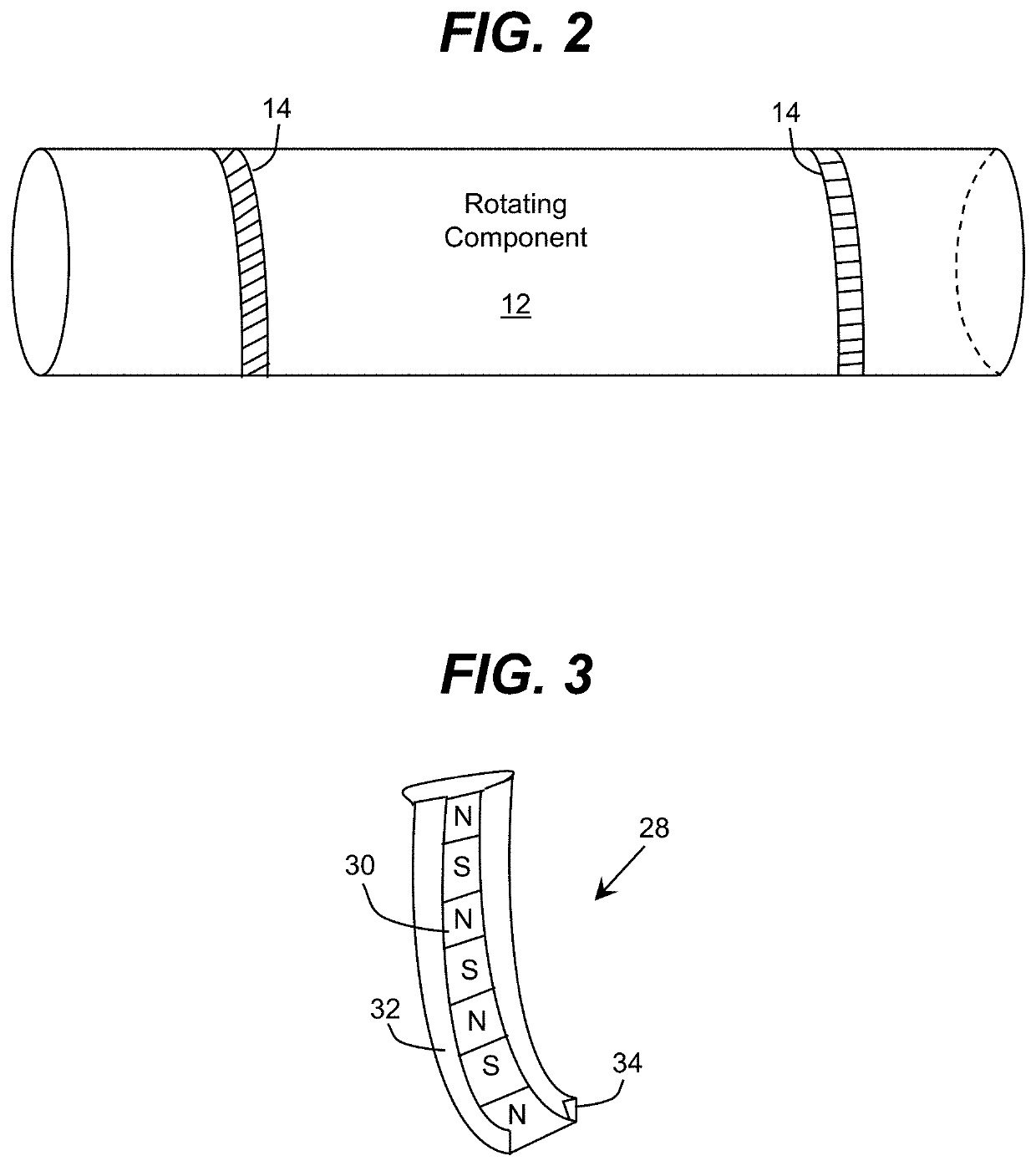
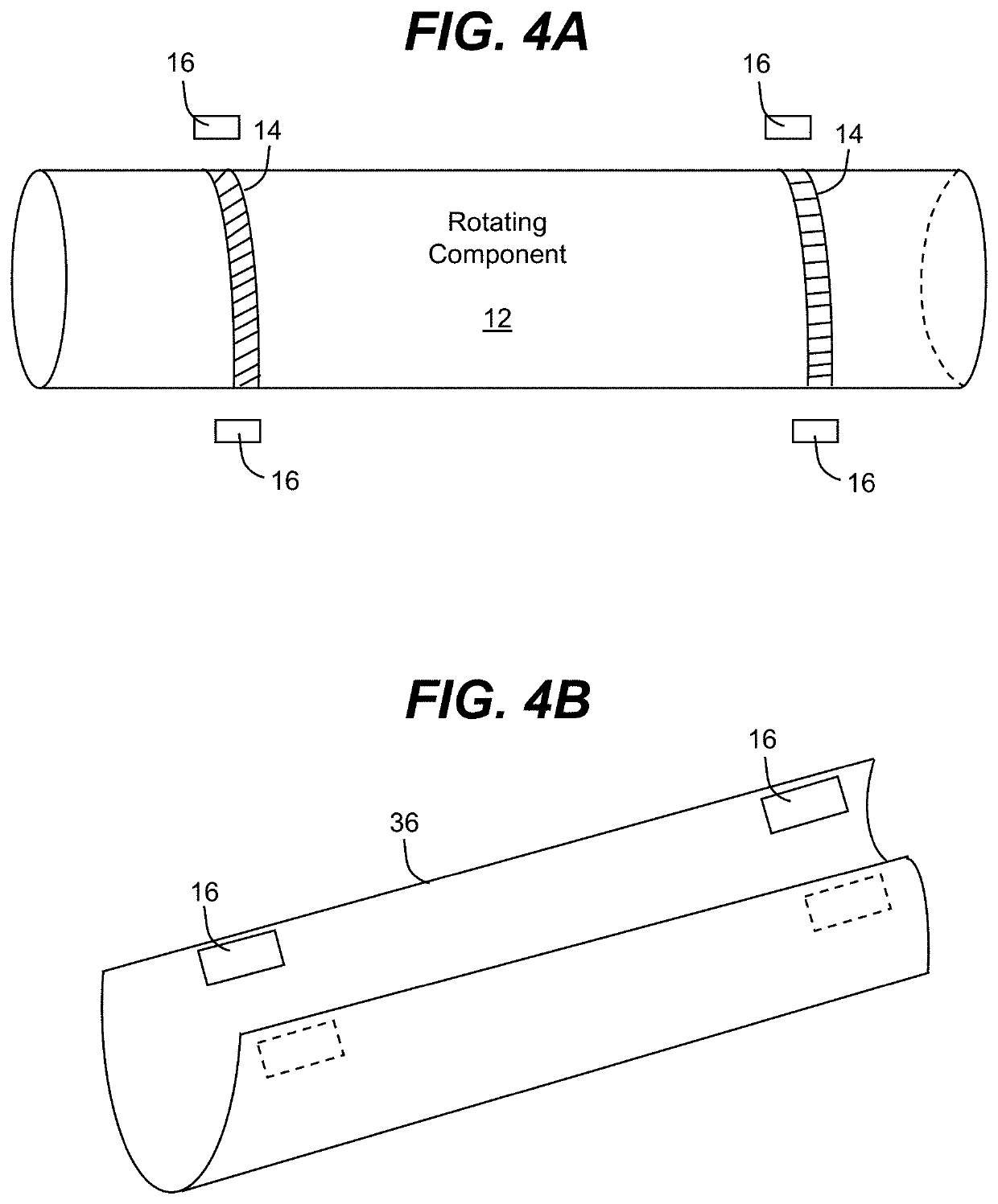
[0033]As indicated above, aspects of the invention are directed to approaches that can measure and monitor torque in a mechanical component, such as a rotating component. These approaches do not involve physical connections and direct modifications to the rotating component for the data acquisition components. Further, these aspects are not limited to very small lift-off levels, but instead can allow for significant lift-off (i.e., greater than one quarter inch). In addition to measuring torque in a rotating component, aspects of the invention are also directed to determining other related parameters such as for example, strain (e.g., twist), rotational speed, rotational displacement and spatial displacement. To this extent, other aspects of the invention are directed to monitoring these measurements and determining how such measurements affect the performance of the rotating component, as well as the impact that the measurements have on the component from structural and / or safety p...


PUM

PropertyMeasurementUnit
physical anglesaaaaaaaaaa
torqueaaaaaaaaaa
strengthaaaaaaaaaa

Abstract

A solution for measuring torque and other parameters of a mechanical component is provided. At least two bands can be affixed to the mechanical component and at least two sensing assemblies can be operatively coupled to each band. Each sensing assembly generates signals indicative of relative movement between a respective band and the sensing assembly. A signal conditioner conditions the signals for a computing unit to determine the torque to the mechanical component. The computing unit can determine the torque from a twist of the mechanical component that can be correlated with the torque.

Description

REFERENCE TO RELATED APPLICATIONS[0001]The present patent application claims the benefit of U.S. Provisional Application No. 62 / 937,561, which was filed on 19 Nov. 2019, and which is hereby incorporated by reference.TECHNICAL FIELD[0002]The disclosure relates generally to mechanical components, such as rotating components, used in machines, and more particularly, to measuring torque and other parameters of the mechanical components without the measuring devices having physical connections to the mechanical components or requiring direct modifications of the mechanical components.BACKGROUND ART[0003]Measurement of torque and other related parameters are useful capabilities in a number of transportation and industrial applications. For example, measuring the torque or strain on a mechanical element such as a rotating component (e.g., a drive shaft) can be used in Health and Usage Monitoring Systems (HUMS) to determine the use of the component and the available or expected lifetime of ...

Claims


Application Information

Patent Timeline
Patent Type & Authority Patents(United States)
IPC IPC(8): G01L3/10
CPCG01L3/105G01L3/109G01L3/101
Inventor MIAN, ZAHID F.MCKENNEY, BRUCEHAYES, PETERPEARLMAN, MARC
Owner INT ELECTRONICS MACHINES
Why Eureka
Try Eureka