
Video speed STN display

a stn display and video technology, applied in static indicating devices, instruments, non-linear optics, etc., can solve the problems of increasing display thickness and weight, overall system complexity, and yellow background of the first stn display, so as to improve the restoration speed and high contrast ratio , the effect of high display quality of motion images

Inactive Publication Date: 2005-06-02
MA YAO DONG
View PDF4 Cites 0 Cited by
  • Summary
  • Abstract
  • Description
  • Claims
  • Application Information

AI Technical Summary

Benefits of technology

[0007] It is again another object of the present invention to adopt a liquid crystal formulation with low viscosity and ultra high optical anisotropy.
[0009] It is still an object of the present invention to dope high concentration of cholesteric twisting agent to the display cell structure to increase restoration speed.
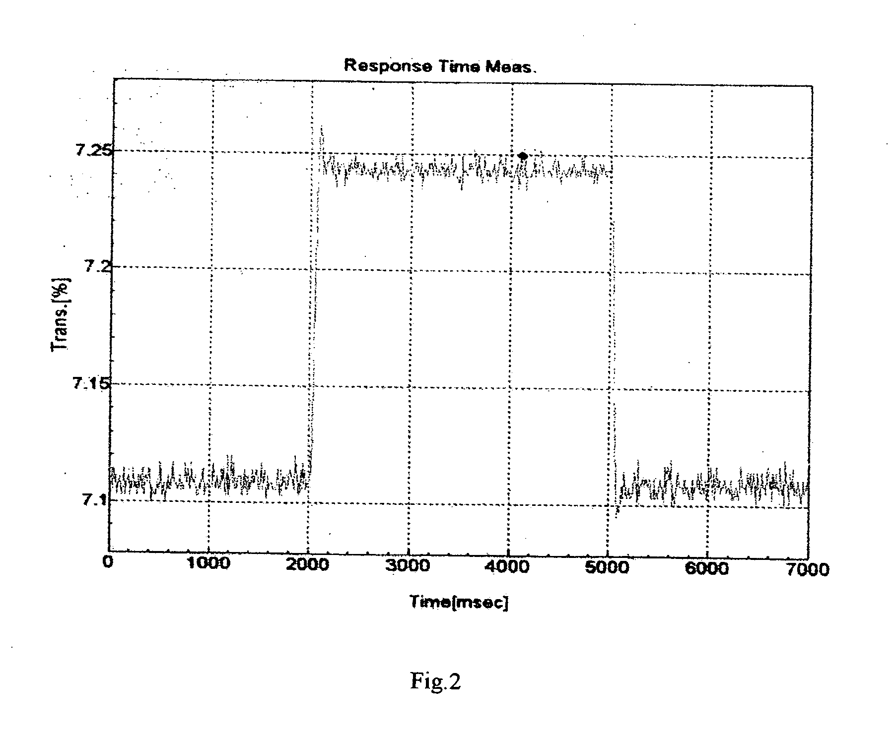
[0014] 2. STN design should not be limited to the first or second minimum transmission as the normal TN does where the wave-guiding mode is necessary. Thus allow the cell gap of the STN display reduced to a very small level, for example, as recommended in the present invention, to 3 μm as long as the And meets the requirement of the optic design. This will be remarkably reduced the response time because of the fact that the response time is inverse proportional to the power of the cell gap. The reduction of the cell gap is a decisive factor to the fast response display.
[0016] 4. To achieve a flicker-free video rate display, a driving waveform has to be designed. It is discovered that when the frame rate of the driving waveform is two times more than the normal frame rate of the prior art, a flicker-free motion image could be obtained. Unlike the prior art multi-line-addressing (MLA), the present invention takes advantage of the single line addressing and normal STN driver chips to realize a simple and economical solution to the video rate STN display. Meanwhile, since the frame rate is remarkably increased, the frequency response and the output performance of the driving circuitry become very important to reduce or eliminated the frame response and the cross talk effect occurred in the dynamic driving process.

Problems solved by technology

The yellow background of the first STN displays was not well accepted by people who is used to the black-and-white and full color display.
Two drawbacks of the double layer STN are the increased display thickness and weight.
But each MLA implementation has its own trade-offs on performance and overall system complexity.
Regardless of the actual implementation, MLA drive schemes have a common problem that circuitry must be available to perform the multiplication and summation required for the inner product.
Economically, the cost for the MLA unit is so high that most LCD producer cannot afford to accept it.
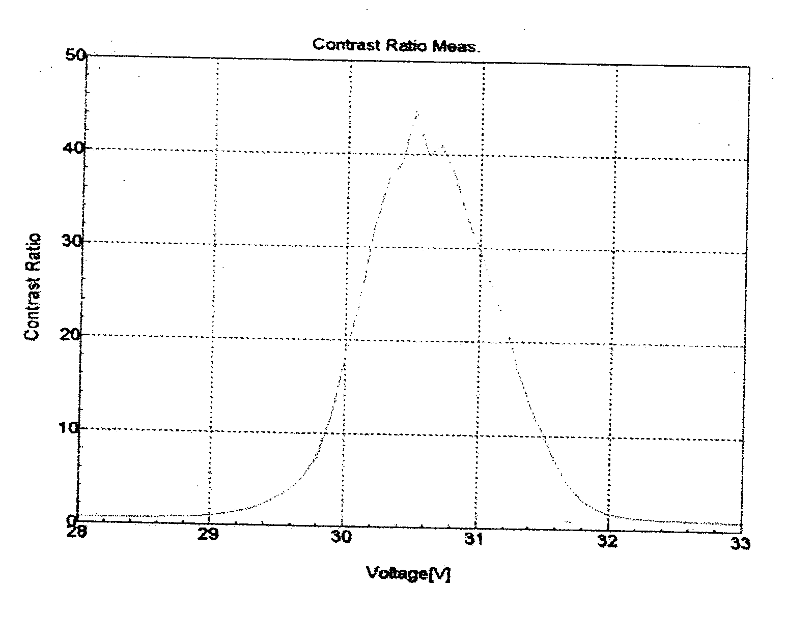
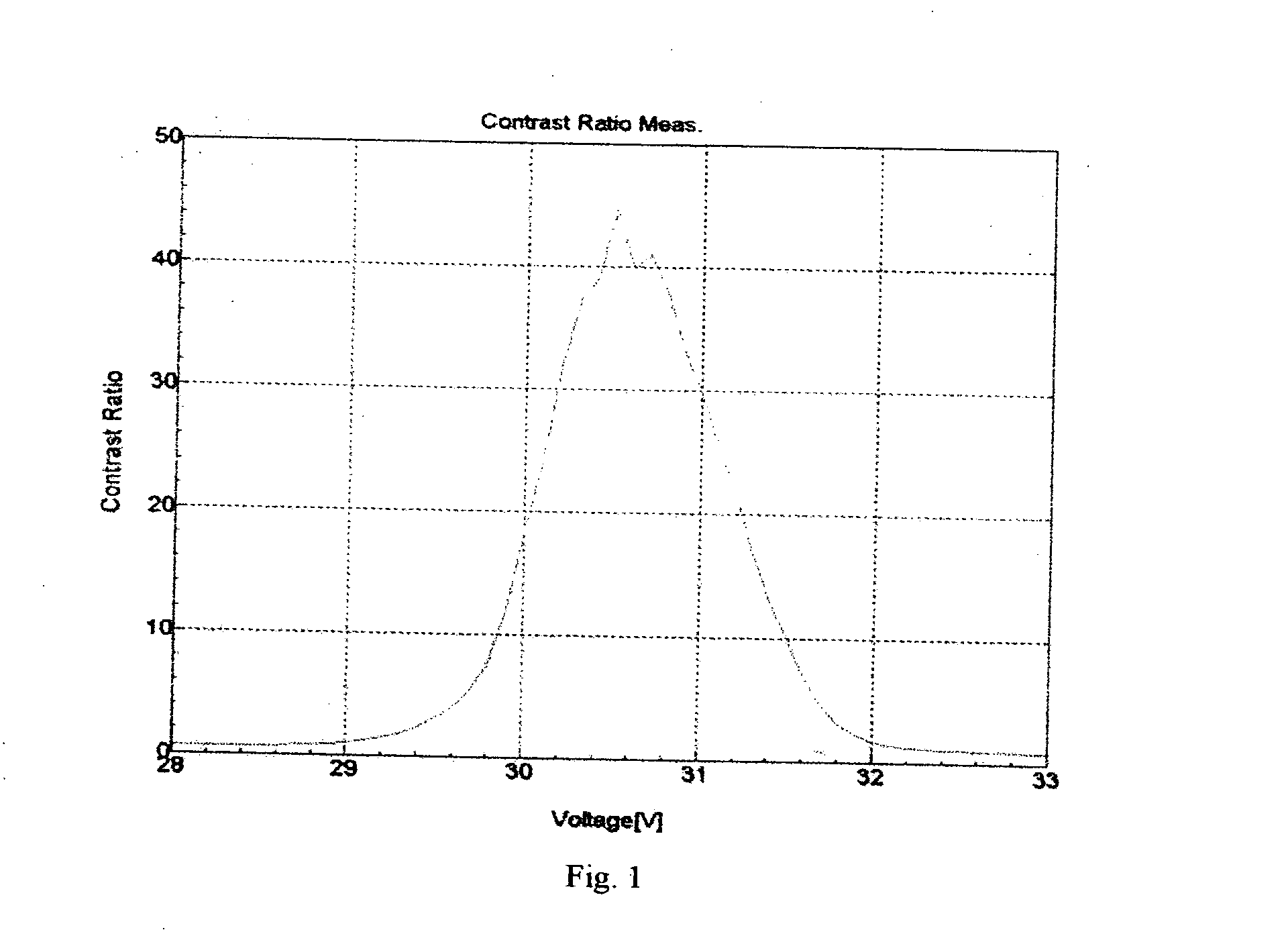
Therefore, video-rate display with high contrast ratio is difficult to realize with the prior art technologies.

Method used


Image

  • Video speed STN display
  • Video speed STN display
  • Video speed STN display

Examples


example

[0028] A video rate color STN sample with dimension of 128 mm×97.4 mm was made according to the following process.

[0029] The substrate materials are touch-polished soda-lime glass with coatings to block ion migration.

[0030] Transparent Indium-Tin Oxide (ITO) coatings are patterned into row and column electrodes on the two substrates. The front glass is 0.7 mm glass with ITO resistivity of 50 Ω / □ and the back glass substrate has a color filter layer, which has the following parameters:

TABLE 1RGBITO (Ω / □)X0.4000.3110.224Y0.3130.3850.277Z50.6674.1746.9513.6Trans.At λ = 620At λ = 530At λ = 46086.981.473.8

[0031] The substrates are spaced apart with randomly dispersed 3.5 μm plastic balls having an area density of 275±25 spacers per mm2 and final cell gap is controlled at 3.3 μm. The liquid crystal material MDI-STN01 is vacuum filled into the display cell resulting the retardation rate Δnd data listed as following:

TABLE 2123Average10.8350.8290.8340.83320.8310.8240.8320.83030.8290.82...


PUM

PropertyMeasurementUnit
thicknessaaaaaaaaaa
thicknessaaaaaaaaaa
twist angleaaaaaaaaaa

Abstract

The present invention relates to a liquid crystal display, especially, to a video speed STN display with high contrast ratio. The display provides not only a flicker-free video speed with 30 frames per second, but also a high display quality, such as full color gamut, high contrast ratio and high brightness and so on. The video speed display is realized by the optimization of the display cell structure, the liquid crystal formulation and the driving circuitry.

Description

FIELD OF INVENTION [0001] The present invention relates to a liquid crystal display, especially, to a video speed STN display with high contrast ratio. The display provides not only a flicker-free video speed with 30 frame per second, but also a high display quality, such as full color gamut, high contrast ratio and high brightness and so on. The video speed display is realized by the optimization of the display cell structure, the liquid crystal formulation and the driving circuitry. BACKGROUND OF THE INVENTION [0002] Super twist nematic (STN) liquid crystal display is characterized by the fact that the information content can be as high as video-graphic-array resolution using a passive matrix drive scheme. As a special TN display, STN was discovered during 1980s that the steepness of the electro-distortional curve could be dramatically increased by increasing the layer twist angle from 90° to 270°. A steep electro-distortional curve is a precondition to achieve high contrast passi...

Claims


Application Information

Patent Timeline
Patent Type & Authority Applications(United States)
IPC IPC(8): G02F1/139G09G3/36
CPCG09G3/3622G02F1/1397
Inventor MA, YAO-DONG
Owner MA YAO DONG
Learn More