
Monitoring system for automatic charging apparatus for vehicle

Inactive Publication Date: 2006-05-30
AISIN SEIKI KK +1
View PDF13 Cites 53 Cited by
  • Summary
  • Abstract
  • Description
  • Claims
  • Application Information

AI Technical Summary

Benefits of technology

[0007]By virtue of this configuration, the judgment as to whether the automatic charging apparatus is in an anomalous state is performed on the basis of information which represents the internal status of the automatic charging apparatus and is transmitted from the transmission means of the automatic charging apparatus only when the vehicle stays at the predetermined position. Therefore, the monitor apparatus hardly misidentifies, as information of an automatic charging apparatus to be monitored, information corresponding to the internal status of an automatic charging apparatus of another vehicle which is different from the vehicle on which the automatic charging apparatus to be monitored is mounted. Therefore, judgment as to presence / absence of anomaly in the automatic charging apparatus can be performed reliably.
[0010]Since monitoring is performed while the vehicle is in a stopped state, it becomes possible to cause the automatic charging apparatus to perform complex calculation which requires a relatively long calculation time, and judge whether the automatic charging apparatus is in an anomalous state on the basis of the result of the calculation. Therefore, accuracy of the judgment as to presence / absence of anomaly can be improved further. Moreover, since the predetermined information which is transmitted from the monitor apparatus to the automatic charging apparatus can be changed, an anomalous state of the automatic charging apparatus caused by altering of the automatic charging apparatus can be detected more accurately, because when the automatic charging apparatus is altered, correct calculation is difficult to be performed for new information.
[0012]Since monitoring is performed while the vehicle is in a stopped state, the judgment as to whether the automatic charging apparatus is in an anomalous state can be performed on the basis of the result of a judgment as to whether the automatic charging apparatus properly performs charge-amount calculation, which requires a relatively long calculation time and is the most important function of the automatic charging apparatus. Further, since the pseudo information which is transmitted from the monitor apparatus to the automatic charging apparatus can be changed, an anomalous state caused by altering of the automatic charging apparatus can be detected more accurately, because when the automatic charging apparatus is altered, correct calculation becomes difficult to perform for new pseudo position information.
[0018]Since this configuration enables the management center or the like to identify a vehicle whose automatic charging apparatus is in an anomalous state, such vehicles can be managed in a centralized manner.

Problems solved by technology

Therefore, there is a possibility that a normal automatic charging apparatus is misidentified as an anomalous automatic charging apparatus of another vehicle.

Method used


Image

  • Monitoring system for automatic charging apparatus for vehicle
  • Monitoring system for automatic charging apparatus for vehicle
  • Monitoring system for automatic charging apparatus for vehicle

Examples


Embodiment Construction

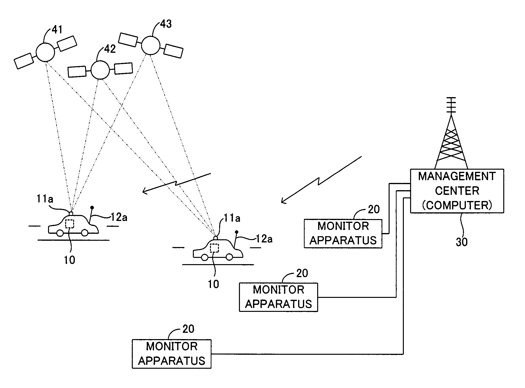
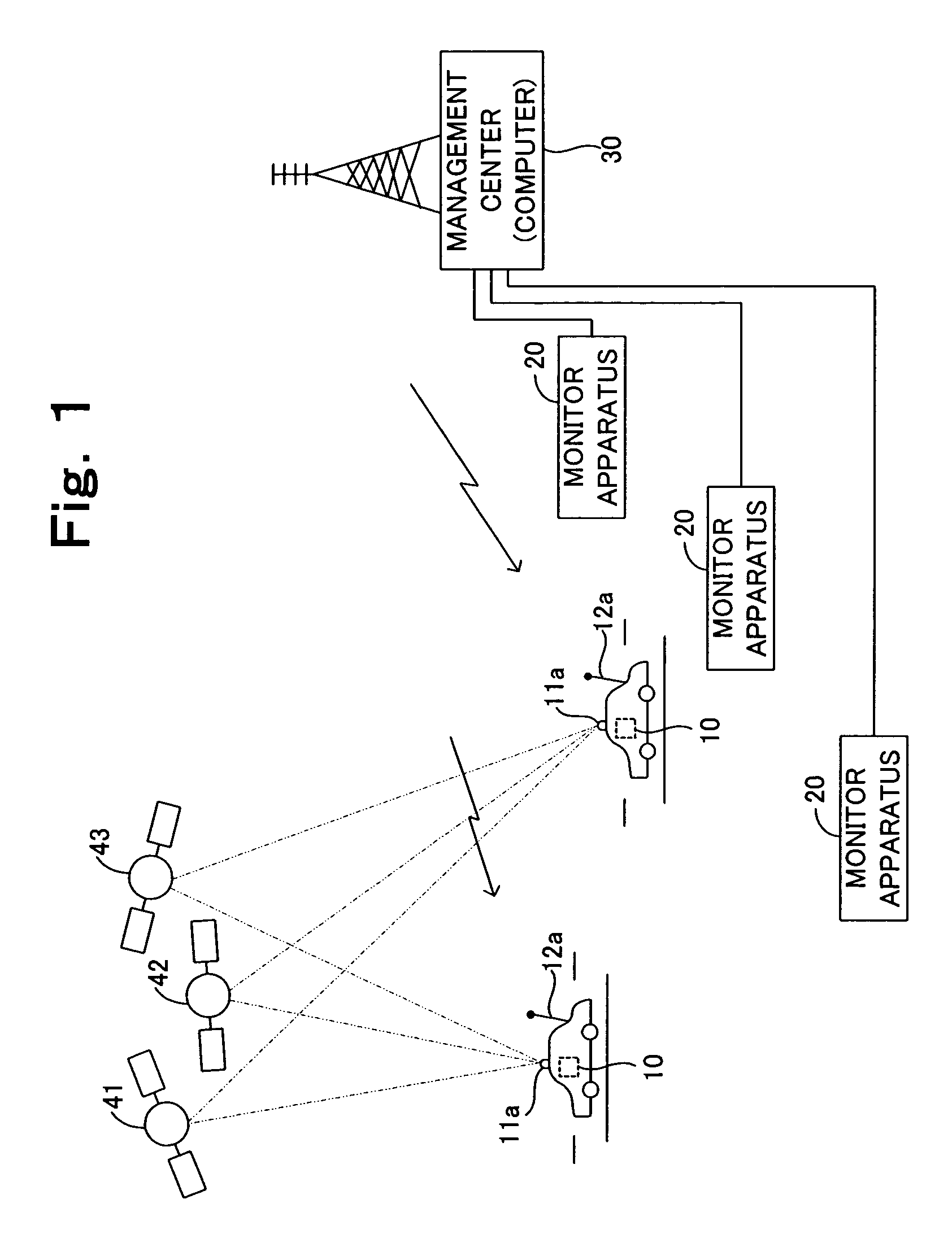
[0030]FIG. 1 is a conceptual view showing the entire configuration of a system for monitoring an automatic charging apparatus for a vehicle according to an embodiment of the present invention. The monitor system includes an automatic charging apparatus mounted on each vehicle (an on-vehicle apparatus) 10; a monitor apparatus 20 disposed at an appropriate location (e.g., a gas station or a repair shop) on the ground; and a management center 30 connected to the monitor apparatus 20 in a communicatable manner.

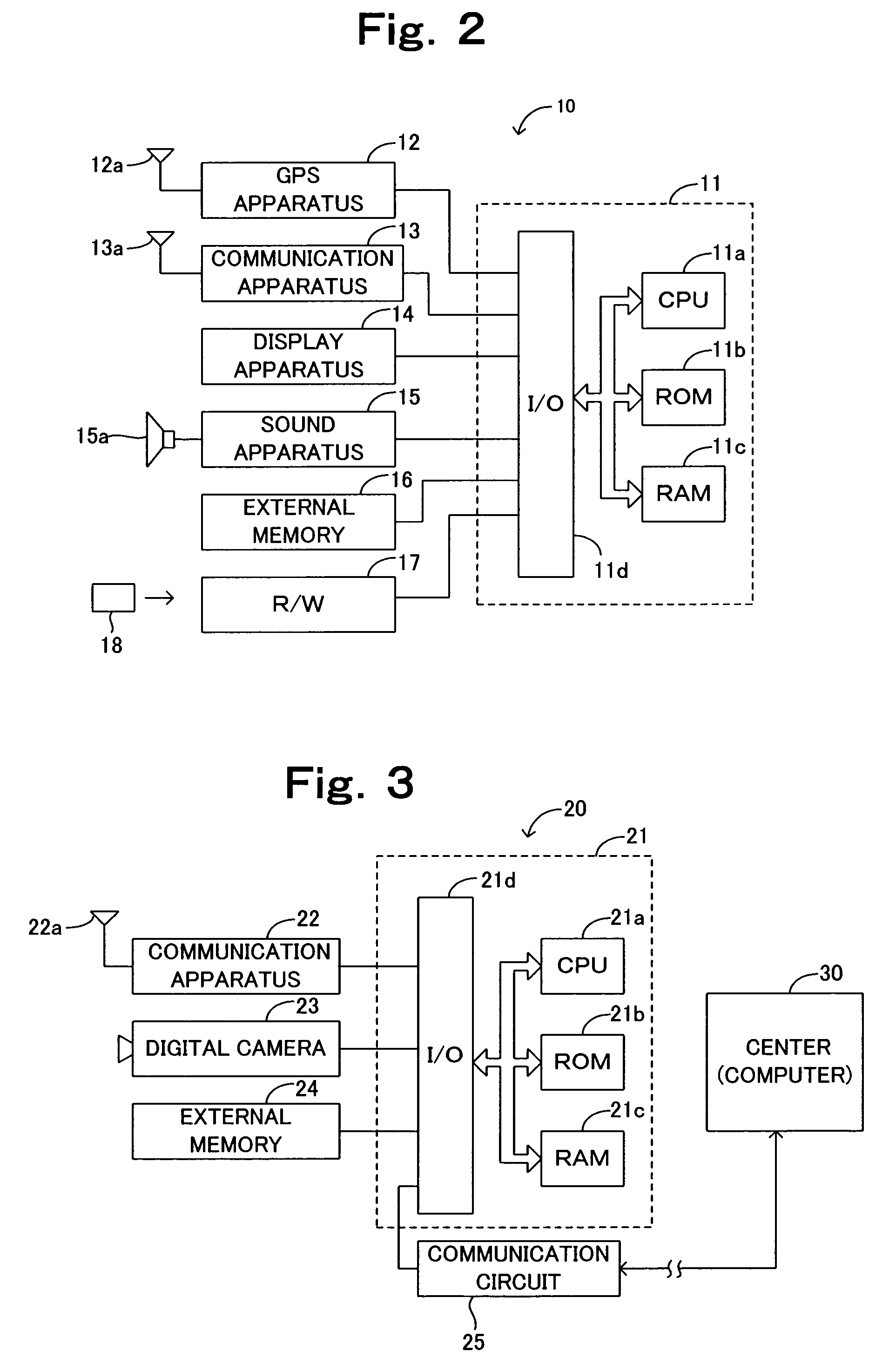
[0031]As shown in FIG. 2, the automatic charging apparatus 10 is mainly composed of a microcomputer 11. The microcomputer 11 includes a CPU 11a, ROM 11b, RAM 11c, and an input / output interface 11d, which are connected with one another via a bus. The CPU 11a executes a program (routine) stored in the ROM 11b, which will be described later, while using the data storage function of the RAM 11c.

[0032]The automatic charging apparatus 10 includes a GPS apparatus 12, a communication app...


PUM


Abstract

When a monitor apparatus judges that a vehicle has stopped at a predetermined position (step 705), the monitor apparatus transmits pseudo position information of the vehicle (dummy data) to an automatic charging apparatus (step 725). The automatic charging apparatus calculates a charge amount on the basis of the dummy data, and transmits the result of the calculation to the monitor apparatus. The monitor apparatus receives the result (step 735) and judges on the basis of the result whether the automatic charging apparatus is in an anomalous state (step 740). Since the above-described successive operations are performed only when the vehicle stays, the status of another automatic charging apparatus not monitored is not misidentified as the status of an automatic charging apparatus to be monitored.

Description

[0001]This application is the National Phase of International Application PCT / JP01 / 08503 filed Sep. 28, 2001 which designated the U.S. and that International Application was not published under PCT Article 21(2) in English.TECHNICAL FIELD[0002]The present invention relates to a monitoring system for an automatic charging apparatus for a vehicle which is mounted on the vehicle and adapted to calculate amounts of money to be charged to the vehicle on the basis of at least position information representing position of the vehicle, as well as to the automatic charging apparatus itself and to a monitor apparatus used in the monitoring system.BACKGROUND ART[0003]There has conventionally been known an automatic charging system which includes an automatic charging apparatus which is mounted on a vehicle and adapted to operate as follows. The apparatus obtains position information representing position of the vehicle by use of, for example, GPS and on the basis of the position information ju...

Claims


Application Information

Patent Timeline
IPC IPC(8): G07B15/00G08G1/00G07B15/06G07C5/00G07F7/00G08G1/123
CPCG07B15/063G08G1/20G07F17/0042G07C5/008G07B15/00G07C5/00
Inventor AOKI, YASUYUKIKAKIHARA, MASAKI
Owner AISIN SEIKI KK
Learn More