RF lightwave coding system for radar pulse compression

a lightwave coding and pulse compression technology, applied in the field of rflightwave system, can solve the problems of phase coding only being used in narrow-band radar systems, generating and processing wideband waveforms, and digital synthesizers generally limited to frequencies of several hundred megahertz

Inactive Publication Date: 2006-05-30
HRL LAB
View PDF10 Cites 25 Cited by
  • Summary
  • Abstract
  • Description
  • Claims
  • Application Information

AI Technical Summary

Benefits of technology

[0014]The RF radar transmit and return waveforms are modulated onto lightwave carriers. A RF-photonic encoder and a decoding preprocessor are used to phase-encode the Transmit waveform and partially decode the return signal. The encoder contains switched optical delay-lines to produce the desired RF phase shifts. The decoding preprocessor is based on a tapped optical delay line. The taps can be weighted to accomplish objectives such as reduction of side lobes in the compressed pulse. By using RF-lightwave encoders and decoders, one can achieve shorter compressed pulses and larger pulse-compression ratios than can be obtained using conventional electronic approaches. The presently disclosed technology is applicable to wideband transmit waveforms since it uses switched optical delay lines and, unlike prior approaches, is not restricted to single-frequency waveforms.

Problems solved by technology

Presently, phase coding has only been used for narrow-band radar systems, partly because of the difficulty of generating and processing wideband waveforms by electronic means.
Digital synthesizers, however, are generally limited to frequencies of several hundred megahertz or lower.
Also, the phase re-shifts generally cannot be changed quickly.

Method used


Image

  • RF lightwave coding system for radar pulse compression
  • RF lightwave coding system for radar pulse compression
  • RF lightwave coding system for radar pulse compression

Examples


Embodiment Construction

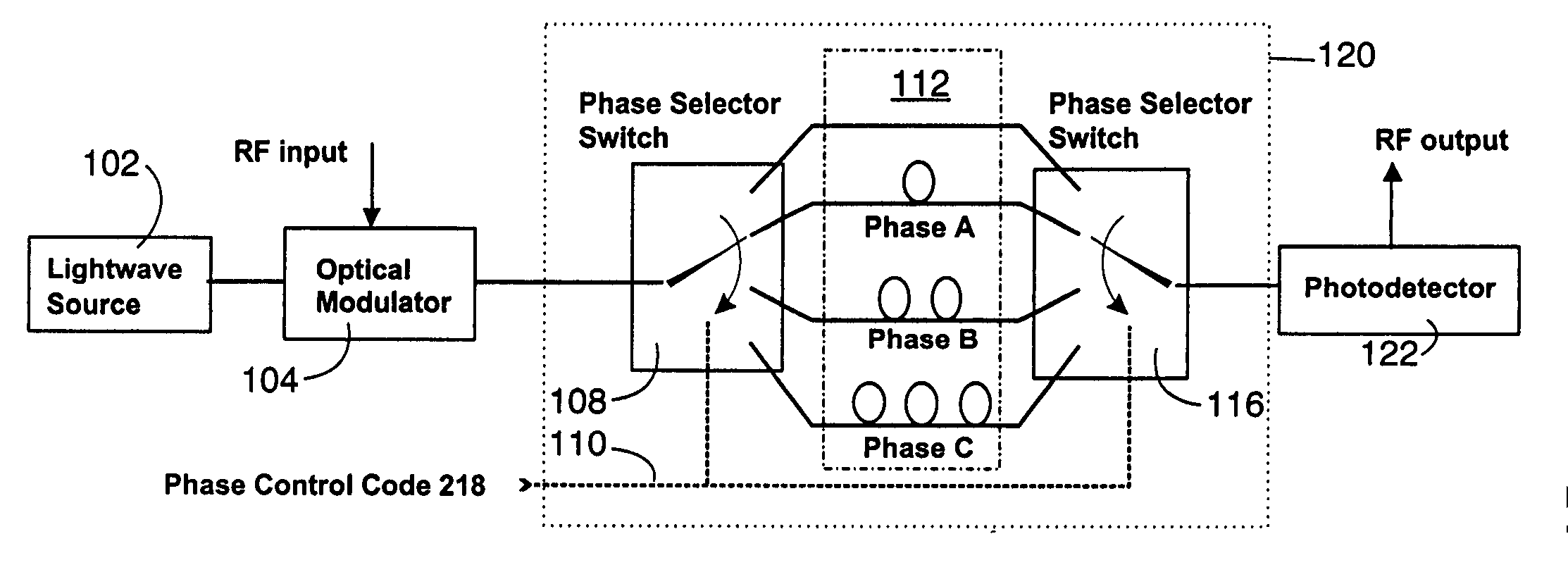
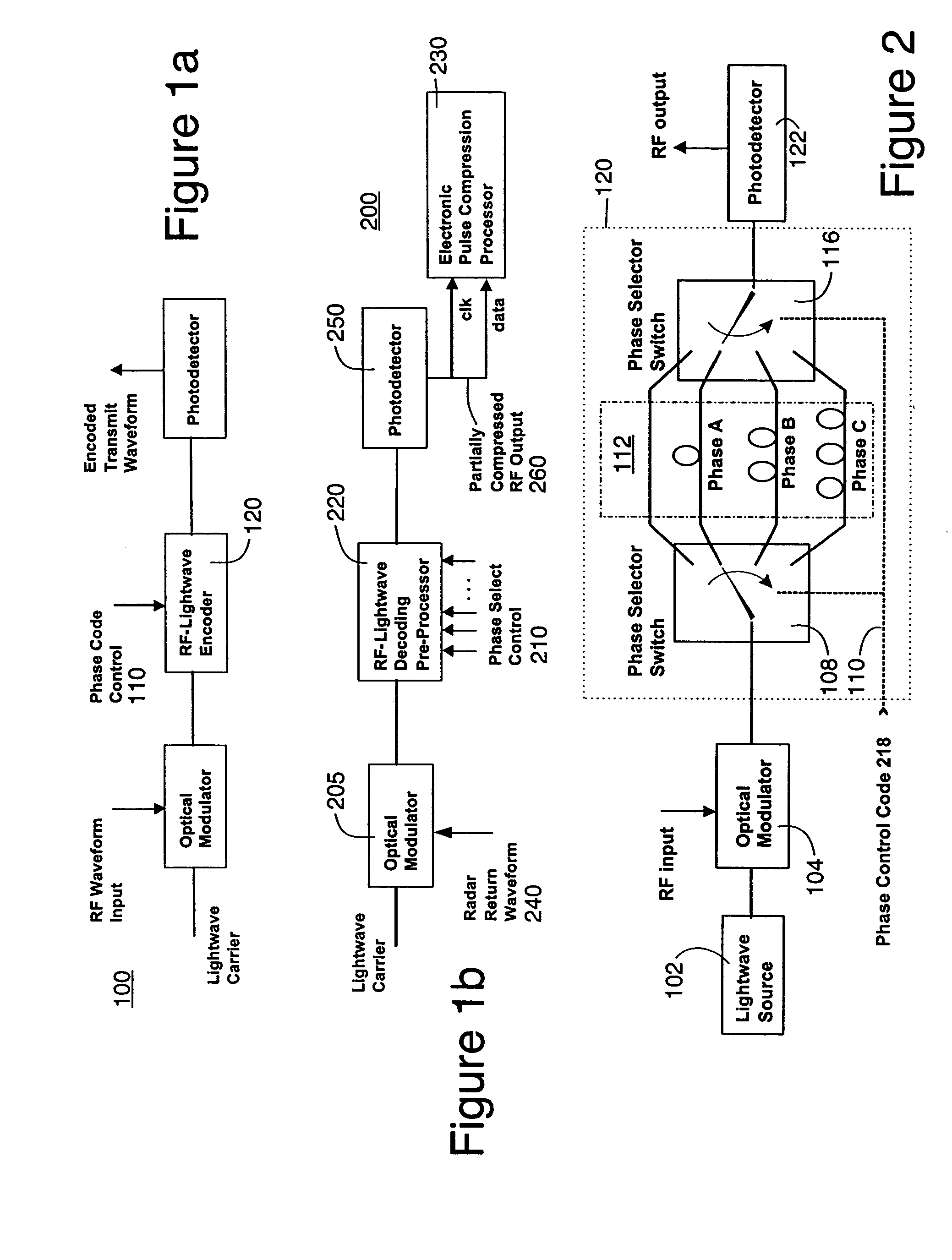
[0025]The RF lightwave time-delay coding system disclosed herein includes a RF-lightwave phase encoder 100 and a phase decoder 200. The phase decoder 200 contains a RF-lightwave time-delay decoding preprocessor 220. Both the encoder 100 and the decoder 200 can have RF inputs and outputs. One or more of their inputs and / or outputs can alternatively be a RF-lightwave port instead of a RF port. For a RF-lightwave port, the signal is in the form of a RF-modulated lightwave carrier. A block diagram of an embodiment of the RF-lightwave phase encoder is depicted by FIG. 1a while the phase decoder is depicted by FIG. 1b. For RF inputs and outputs, the system also includes optical modulators and photodetectors that transduce the signal from the RF domain into the RF-lightwave domain.

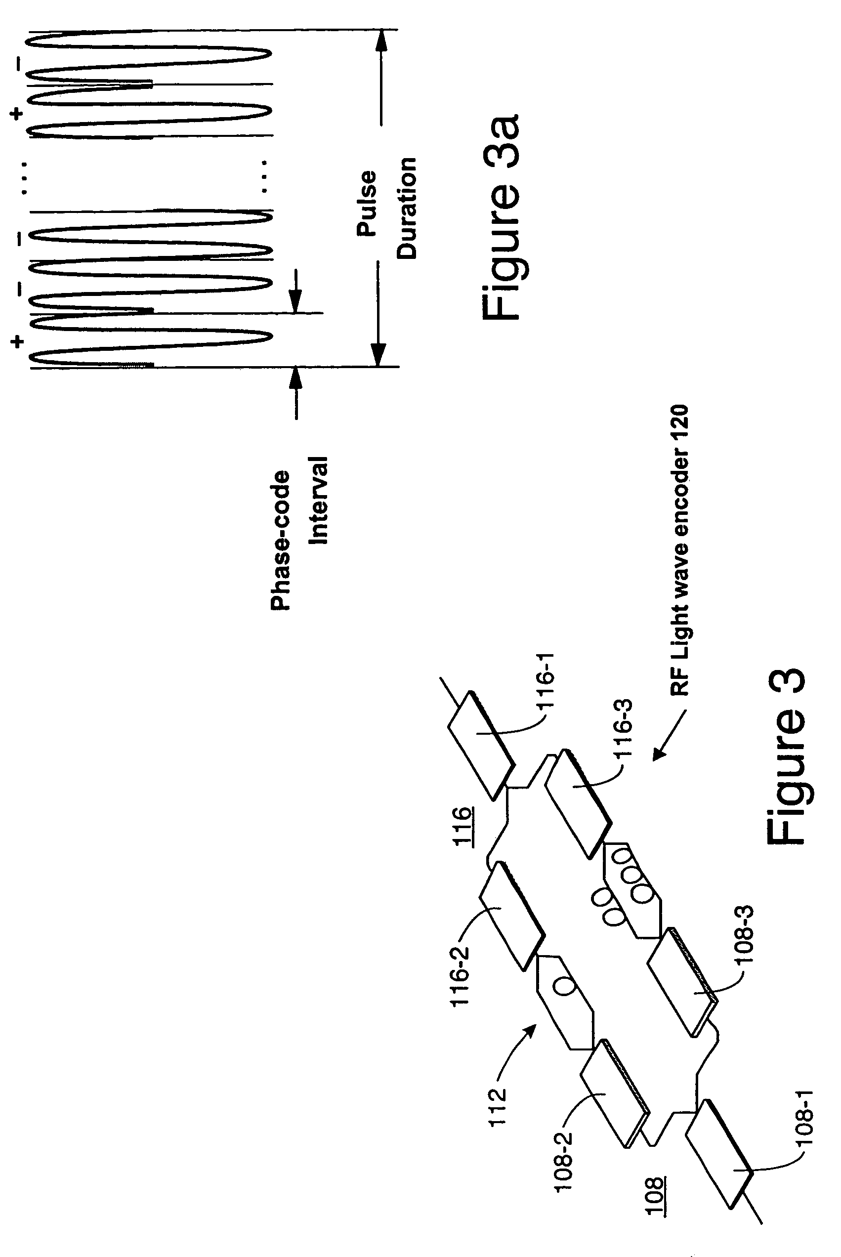
[0026]A phase-code control signal data stream or sequence is supplied via a control input 110 to the RF lightwave encoder 120. The control signal 218 on this control input 110 can be a binary data stream if the p...


PUM


Abstract

An apparatus for preparing a RF radar transmit waveform and for decoding RF return waveforms comprising: a RF-lightwave encoder and a decoding preprocessor to phase-encode the RF radar transmit waveform and partially decode the return signal, the encoder including switched optical delay lines for producing desired RF phase shifts, and the decoding preprocessor including a tapped optical delay line and optical delay lines that counteract the delays imposed by the delay lines of the encoder, wherein the RF-lightwave encoder and the decoders allow shorter compressed pulses and larger pulse-compression ratios to be achieved than can be obtained using conventional electronic approaches. Wideband transmit waveforms can be generated due to the use of the switched optical delay lines and, unlike prior art approaches, is not restricted to single-frequency waveforms. The taps can be weighted to accomplish objectives such as reduction of side lobes in the compressed pulse.

Description

STATEMENT OF GOVERNMENT INTEREST[0001]This invention was related to work performed under the government contract No. F33615-02-C-1184″. The government has certain rights in this invention. TECHNICAL FIELD[0002]The technical field of the disclosed technology relates to a RF-lightwave system for temporal compression of RF pulsed waveforms. This allows a radar system to have a longer detection range and also improved range resolution.BACKGROUND INFORMATION[0003]Most radar systems, especially those that have lower probability of interception (LPI), operate at limited average transmit powers. LPI systems also may involve wideband transmit waveforms (spread spectrum) instead of single-frequency waveforms. In order to increase the detection range of these radar systems, transmit pulses of longer duration, or even continuous (cw) waveforms, are often used. However, the range resolution is reduced as the pulse is lengthened. Pulse compression techniques are available that sub-divide the puls...

Claims


Application Information

Patent Timeline
Patent Type & Authority Patents(United States)
IPC IPC(8): G01S13/86G01S7/28G01S13/28
CPCG01S13/288G01S7/28
Inventor YAP, DANIEL
Owner HRL LAB
Why Eureka
Try Eureka