Interconnect and gateway protection in bidirectional ring networks

a bidirectional ring network and gateway protection technology, applied in the field of communication networks, can solve problems such as bandwidth limitations, and achieve the effect of reducing hardware complication and cost, and accelerating traffic flow

Active Publication Date: 2006-05-30
ORCKIT IP LLC
View PDF73 Cites 25 Cited by
  • Summary
  • Abstract
  • Description
  • Claims
  • Application Information

AI Technical Summary

Benefits of technology

[0008]It is a further object of some aspects of the present invention to provide interconnect nodes for use in bidirectional ring networks that enable rapid resumption of traffic flow in the case of a failure.
[0009]It is a further object of some aspects of the present invention to reduce the levels of hardware complication and cost of interconnect nodes in a bidirectional ring network.

Problems solved by technology

Assuming that the other network to which the interconnect node is linked is also a bidirectional ring network, the same coupling scheme and bandwidth limitations apply to the module connections on both of the networks.

Method used


Image

  • Interconnect and gateway protection in bidirectional ring networks
  • Interconnect and gateway protection in bidirectional ring networks
  • Interconnect and gateway protection in bidirectional ring networks

Examples


Embodiment Construction

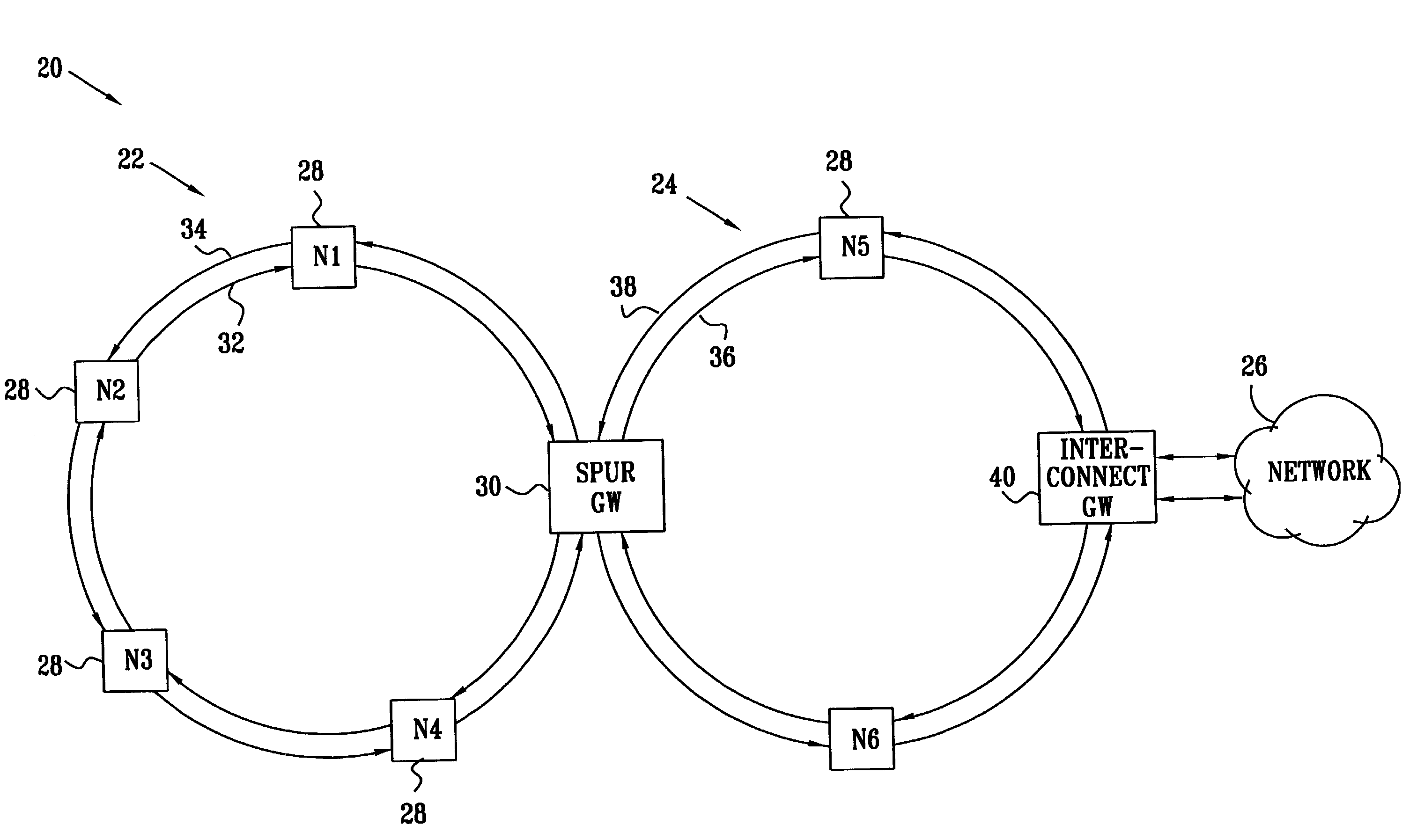
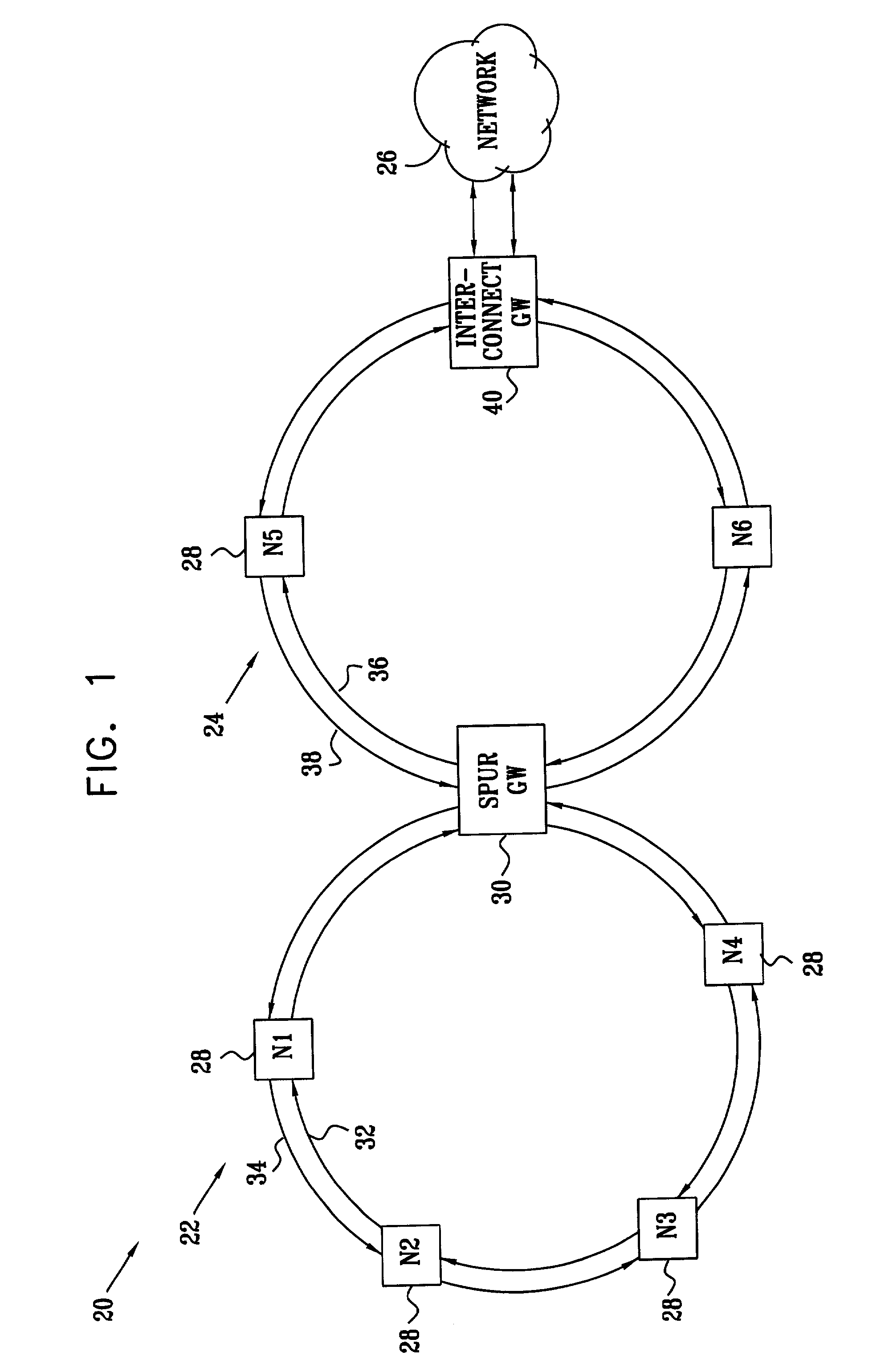
[0034]FIG. 1 is a block diagram that schematically shows a network communication system 20, in accordance with a preferred embodiment of the present invention. System 20 comprises an access (or “spur”) ring network 22, which is coupled to a trunk (or “metro”) ring network 24 by a spur gateway 30. Network 24 is in turn coupled to another network 26, which is not necessarily a ring network, by an interconnect gateway 40. Gateways 30 and 40 are also referred to herein as interconnect nodes. The topology of system 20 is shown here by way of example, for illustrating the operation of gateways 30 and 40, and the extension of the principles described herein to other topologies will be apparent to those skilled in the art.

[0035]In addition to gateways 30 and 40, networks 22 and 24 typically comprise nodes 28. The nodes in each network are mutually connected by bidirectional communication media, such as optical fibers or conductive wires. The nodes typically comprise switching equipment, and...


PUM


Abstract

A communication device for interconnection of first and second networks, of which at least the first network is a bidirectional ring network, includes first and second interconnect modules, each such module adapted to receive outgoing data traffic on the first network at a data rate not substantially greater than a predetermined maximum rate for one of the ring directions, and to convey the outgoing data traffic to the second network. When a fault occurs in one of the first and second modules, the other module is reconfigured to receive substantially all of the outgoing data traffic and to convey the outgoing data traffic to the second network regardless of whether the outgoing data traffic is transmitted on the first network in the clockwise or in the counterclockwise direction.

Description

FIELD OF THE INVENTION[0001]The present invention relates generally to communication networks, and specifically to high-speed packet rings.BACKGROUND OF THE INVENTION[0002]Network ring topologies are gaining in popularity, particularly in Internet Protocol (IP) networks. Such networks enable carriers to offer large bandwidth to users in a cost-effective manner. They also lend themselves to fast rerouting in the event of network failures, since two alternative routes—in clockwise and counterclockwise directions—are generally available for connecting any two nodes on the ring. A drawback of traditional ring implementations, such as SONET / SDH, is that one of the directions is designated as the active ring, while the other direction remains on standby for fault protection when needed. In other words, at any given time, all of the nodes in the ring transmit and receive data only in the active direction. Therefore, ordinarily half of the available bandwidth in these rings is reserved for ...

Claims


Application Information

Patent Timeline
Patent Type & Authority Patents(United States)
IPC IPC(8): G01R31/08G06F11/00H04J1/16H04J3/14H04L12/26H04J3/08H04L12/46H04L12/56
CPCH04J3/085H04L45/28H04L45/00H04L12/4637
Inventor MOR, GAL
Owner ORCKIT IP LLC
Why Eureka
Try Eureka