Information terminal and information terminal system

a technology of information terminals and information terminals, applied in the field of information terminals and information terminal systems, can solve the problem that the extension service is not possible in other terminals, and achieve the effect of easy addition and removal of telephone sets and easy addition and removal

Inactive Publication Date: 2006-05-30
PANASONIC CORP
View PDF11 Cites 77 Cited by
  • Summary
  • Abstract
  • Description
  • Claims
  • Application Information

AI Technical Summary

Benefits of technology

[0011]The invention is devised in the light of the prior art described above, and it is hence an object thereof to present an information terminal capable of using extension service in other information terminal during outside call, realizing a telephone number system integrated according to one concept in telephone network, and easily adding and removing telephone sets.
[0012]To achieve the object, the information terminal of the invention comprises a telephone line interface as an extension interface and a network interface, and specifically the invention presents an information terminal and an information terminal system having each information terminal provided with an identification address for recognizing each information terminal, and capable of adding easily by communication with other information terminal by means of the identification address.

Problems solved by technology

However, since the audio signal frequency bands 19, 20 are used both in an outside call from the information terminal and in extension service, if there are two service bands only, that is, audio signal frequency bands 19 and 20 only, while one information terminal is busy with outside call, extension service is not possible in other terminal.

Method used


Image

  • Information terminal and information terminal system
  • Information terminal and information terminal system
  • Information terminal and information terminal system

Examples


embodiment 1

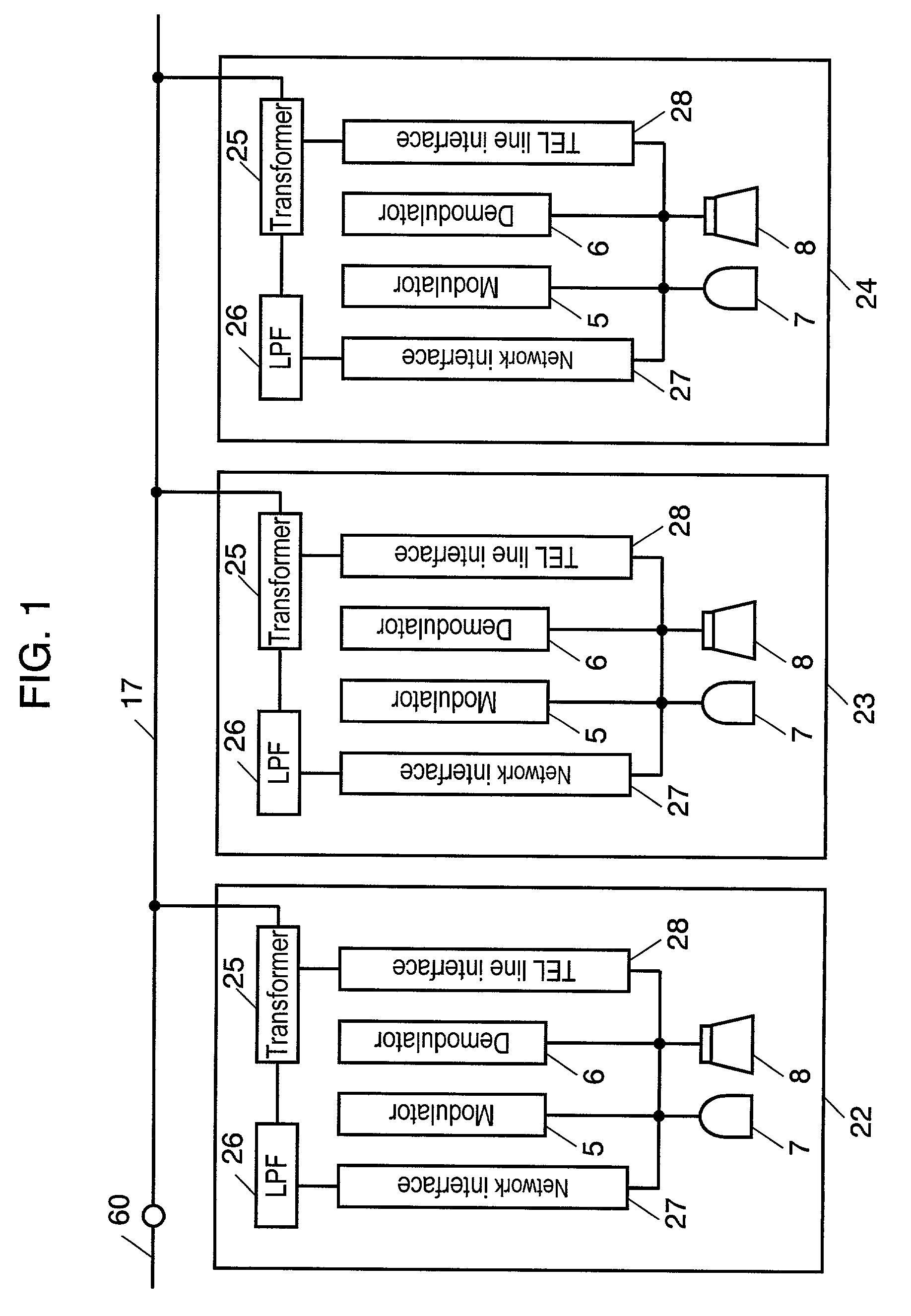
[0037]FIG. 1 is a block diagram showing a configuration of information terminal and information terminal system in embodiment 1 of the invention.

[0038]In FIG. 1, plural information terminals are connected to a private telephone line 17, and the private telephone line 17 is connected to the subscriber's line 60 leading to the exchange, so that the plural information terminals 22, 23, 24, . . . are connected parallel to the subscriber's line 60 through the private telephone line 17. In FIG. 1, the same reference numerals as in FIG. 22 relating to the prior art have the same functions.

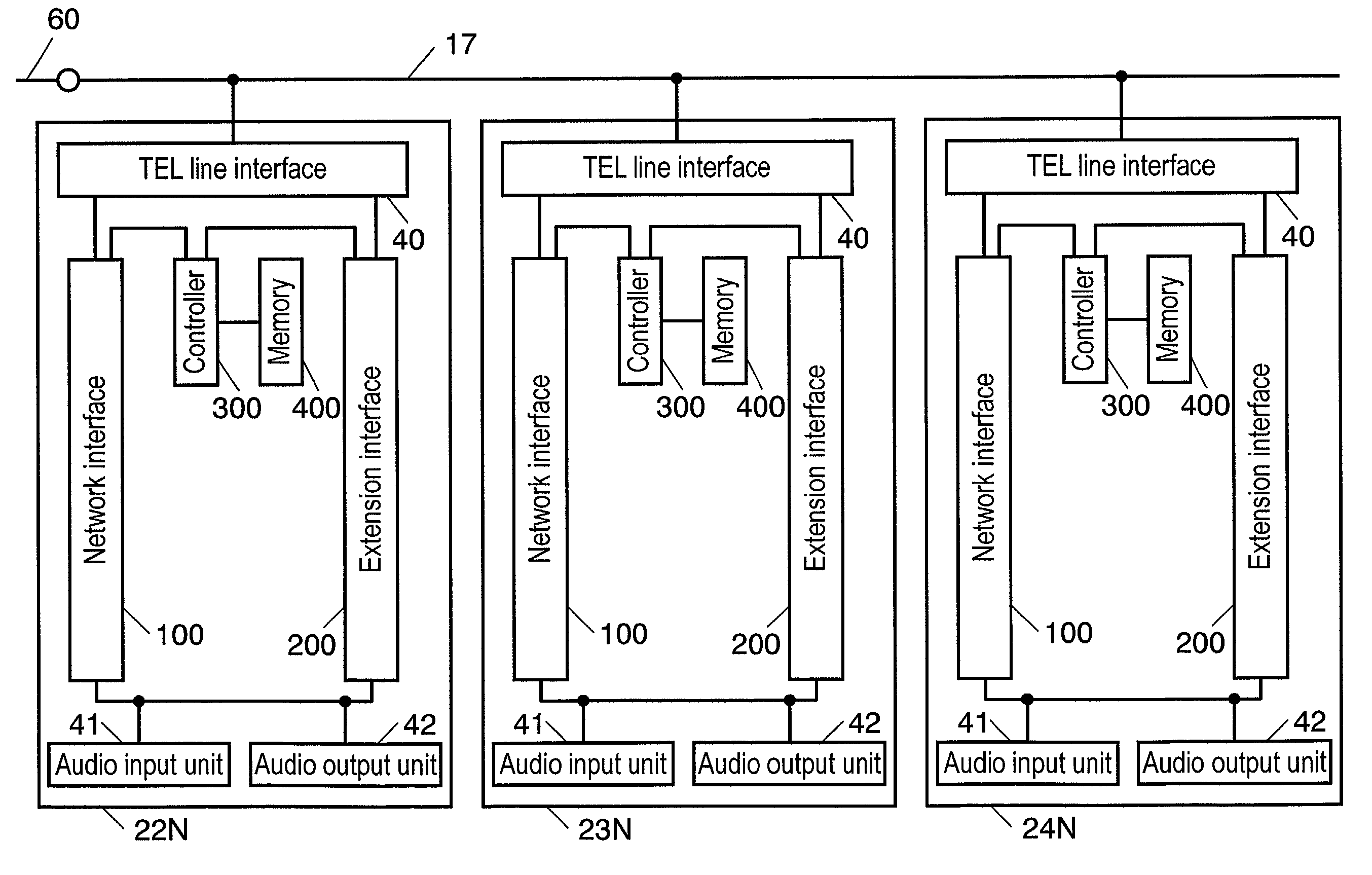
[0039]In the information terminals 22, 23, 24, a transformer 25 sends and receives analog and digital signals to and from the private telephone line 17. A low pass filter (LPF) 26 passes only analog signals. A network interface circuit 27 is a converting circuit for analog telephone. A telephone line interface circuit 28 which is an extension interface is a circuit for sending and receiving packetized dig...

embodiment 2

[0050]FIG. 3 is a block diagram showing a configuration of information terminal and information terminal system in embodiment 2 of the invention.

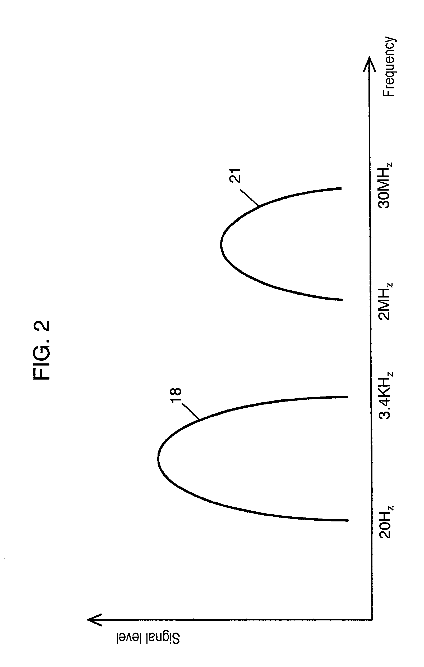
[0051]In FIG. 3, the same reference numerals as in embodiment 1 in FIG. 1 have the same functions. Information terminals 22A, 23A, 24A send and receive digital signals to and from the private telephone line 17 through the transformer 25. The telephone line interface circuit 28 is a circuit for sending and receiving packetized digital information signals through the private telephone line 17 by the CSMA / CD system. In embodiment 2, only the signal frequency band 21 of packetized digital information signals for sending and receiving in FIG. 2 is used, and the outside call is also given by packetized digital data.

[0052]In the information terminal having such configuration, the operation is explained below.

[0053]The flow of an audio signal in the case of outside call sent from the information terminal 22A is as follows. The audio signal entered ...

embodiment 3

[0057]FIG. 4 is a block diagram showing a configuration of information terminal and information terminal system in embodiment 3 of the invention. In FIG. 4, the same reference numerals as in embodiment 1 in FIG. 1 have the same functions. An address controller 29 controls the extension service by individual identification addresses of information terminals 22B, 23B, 24B.

[0058]Identification addresses may be Media Access Control (MAC) addresses used in ordinary LAN, Internet protocol (IP) addresses, or original addresses. In the information terminals 22B, 23B, 24B, the transformer 25 sends and receives analog and digital signals to and from the private telephone line 17. The LPF 26 passes only analog signals. A network interface circuit 27 is a conversion circuit for analog telephone. A telephone line interface circuit 28 is a circuit for sending and receiving packetized digital information signals to and from the private telephone line 17 by the CSMA / CD system. The system frequency ...


PUM


Abstract

An information terminal incorporates a network interface and an extension interface, and in the case of outside call, an audio send signal is modulated into an audio signal frequency band, and sent to the exchange through a private telephone line and a subscriber's line by way of the network interface. An audio receive signal sent from the exchange through the subscriber's line and private telephone line is demodulated into an ordinary audio frequency band through the network interface. On the other hand, in the case of extension service, an audio send signal is converted into a packetized digital signal by an extension interface circuit, and is further modulated into a higher frequency band so as not to overlap with the audio signal frequency band, and is transmitted through the private telephone line.

Description

FIELD OF THE INVENTION[0001]The present invention relates to an information terminal and an information terminal system having outside call and extension functions.BACKGROUND OF THE INVENTION[0002]To begin with, a conventional information terminal is explained.[0003]FIG. 22 is a configuration diagram of a conventional extension telephone system, and FIG. 23 is a frequency band diagram for audio signal of the conventional extension telephone system. The operation is explained below while referring to FIG. 22 and FIG. 23.[0004]Hitherto, the information terminal having the extension function is classified into a main apparatus 1 and information terminals 2 and 3.[0005]The flow of an audio signal for an outside call sent from the information terminal 2 is as follows: the audio signal entered from a microphone 11 is modulated by a modulator 9 into an audio signal frequency band 19 in FIG. 23, and is demodulated into an ordinary audio signal (telephone signal frequency band 18 in FIG. 23)...

Claims


Application Information

Patent Timeline
Patent Type & Authority Patents(United States)
IPC IPC(8): H04L12/66H04B3/54H04L12/413H04M1/715H04M11/06
CPCH04B3/54H04M11/062H04M1/723H04B2203/5416H04B2203/545H04B2203/5445H04M1/715
Inventor MIYAZAKI, TOMIYATAKEDA, YUTAKAYAHIRO, KAZUOTSUJIGAWA, TAKUJIKOGA, NAOKIOGATA, KEISUKEARITAKA, AKITOSHI
Owner PANASONIC CORP
Why Eureka
Try Eureka