Apparatus and method for detecting or recognizing pattern by employing a plurality of feature detecting elements

a technology apparatus, which is applied in the field of apparatus and method for detecting or recognizing patterns by employing a plurality of feature detecting elements, can solve the problems of limited information processing capability, no methods available, and application limitation to the processing of digital representations of information, so as to improve the information processing capability for detecting patterns and high accuracy the effect of detection of a predetermined pattern

Inactive Publication Date: 2006-05-30
CANON KK
View PDF33 Cites 127 Cited by
  • Summary
  • Abstract
  • Description
  • Claims
  • Application Information

AI Technical Summary

Benefits of technology

[0044]Accordingly, it is an object of the present invention to provide a pattern detecting apparatus that enables highly accurate detection of a predetermined pattern by using a smaller circuit, by dramatically improving an information processing capability for detecting patterns.
[0046]It is yet another object of the present invention to achieve a low-cost neural network with a simple construction by reducing the number of wiring involved in connection between neurons.
[0048]It is a further object of the present invention to provide an apparatus and a method for detecting patterns that are capable of efficiently shifting attended positions when a plurality of objects that belong to the same category exist at a plurality of positions in input data.

Problems solved by technology

In implementing the prior arts mentioned above by using circuitry or the like, especially concerning the application to image recognition, there have been no methods available for representing information regarding a two-dimensional pattern by utilizing dynamic characteristic on a time base, and using the represented information for recognition or the like at any level of an a processing device, a module, or a system, which makes up a function of each processing unit (e.g. the extraction of a feature).
In addition, the application has been limited to the processing in a domain of digital representation of information.
For the reason described above, the information processing capability has been limited, and the implementation in the form of circuitry tends to inevitably involve an unduly large scale and high cost.
In particular, the proportion of a large number of wiring for the connection among neurons has been considerably high in the entire area, and this has been posing a problem.
The AER, however, has been presenting a problem in that a device for sequentially coding and decoding the addresses of neurons is required, making a circuit configuration complicated.
However, no literature, including the literature concerning PCNN mentioned above has disclosed any specific configurations based on a neural network in a method for implementing a recognition function by utilizing analog information, such as the interval between spikes, of a train of spikes in a time base domain for the coding or the like of image information in a neural network model for carrying out predetermined processing by inputting, outputting, or transmitting trains of spikes.
Thus, a method in which the conventional predetermined mapping conversion (conformal mapping conversion, etc.) is performed to implement pattern recognition wherein recognition performance is invariant on objects to be recognized that have different scales has been posing a problem in that it is difficult to obtain scale-invariant features unless the central point of conversion is properly set.
The method based on the template matching has been presenting a problem in terms of practicality in that, when performing matching with the template models in different scales that have been represented beforehand, high recognition performance cannot be achieved unless an object in an input image substantially matches with one of the scales, meaning that numerous different template models are required.
This method, however, has been presenting a problem in that the dimension of covariance matrix is large (e.g., 16,384 dimensions in the case presented by Murase and Nayar in 1995), inevitably requiring enormously high cost for calculating eigenvectors.
This has been requiring an extremely large memory space and an enormously long time for computation to complete the processing.
Therefore, to perform scale-invariant recognition, it is necessary to provide a sufficiently high multiplexing level of resolutions to be prepared beforehand, leading to poor processing efficiency.
For this reason, the method may be suited for acquiring rough information by using less memories, but unsuited for recognition or detection requiring high accuracy.
The method based on the dynamic routing network (Anderson et al., 1995; Olshausen et al., 1995) requires a mechanism for dynamically setting the connection between nerve cell elements between predetermined scale levels by a local competing process among control neurons, thus presenting a problem in that the circuit configuration inevitably becomes complicated.
1992) is based on time-series images, making it inherently difficult to accomplish scale-independent recognition from a single still picture.
Hence, a neural circuit of approximately as large as the neural circuit corresponding to the ascending signal pathway is required as a circuit that forms the descending signal pathway, disadvantageously resulting in an extremely large circuit scale.
In addition, this method is provided with no mechanism for controlling the sequential change of fixation positions, posing a problem in that the operation is unstable when setting or changing an attended region due to the influences of noises or other factors.
This has been presenting a problem in that, if there are a plurality of objects that fall within the same category, then the positions of fixation points are not controlled to sequentially shift among the objects in a stable manner, causing a fixation position to librate only between particular objects or in the vicinity thereof.
There has been another problem in that, if there are a plurality of objects that fall within the same category as that of an object to be detected or recognized in input data, then subtle adjustment of network parameters must be made whenever processing for a plurality of objects (substantially non-attention processing) simultaneously occurs or whenever attention position updating is performed.
In the system based on the selective routing described above, in the control of attended positions, it is not easy to efficiently control the attended position because the system is equipped only with a mechanism for inhibiting a selected region.
However, the system using the dynamic routing network reconfigures interlayer connection through the intermediary of many control neurons for which synaptic connection weight can be dynamically changed, so that the circuit configuration inevitably becomes complicated.
In addition, the control neurons involve bottom-up processing based on the feature salience level of a lower layer, so that it has been difficult to achieve efficient control of attended positions if a plurality of objects of the same category are present.
This has been posing a problem in that, if a plurality of objects are present, then it is not easy to efficiently control the positions of fixation points.
Firstly, none of the systems described above are provided with mechanisms capable of dealing with different sizes of objects to be recognized.
Secondly, if there are a plurality of objects that belong to the same category at a plurality of positions in input data, it has been impossible to evenly and efficiently shift or update attended positions across the objects.
On the other hand, however, the circuit configurations using analog circuit elements have been presenting problems with immunity to noises, and reliability of input / output features attributable to variations in the characteristic of individual elements.

Method used


Image

  • Apparatus and method for detecting or recognizing pattern by employing a plurality of feature detecting elements
  • Apparatus and method for detecting or recognizing pattern by employing a plurality of feature detecting elements
  • Apparatus and method for detecting or recognizing pattern by employing a plurality of feature detecting elements

Examples


first embodiment

[0092]A first embodiment in accordance with the present invention will now be described in detail with reference to the accompanying drawings.

[0093]According to the embodiment, to accomplish pattern recognition by using a neural network, spatial pattern information is represented by using dynamic neural features (e.g., the spatiotemporal firing feature of a spike train, the input feature obtained by spatiotemporal integration by a neuron, and spike intervals of a spike train) in the time domain. Thus, the information processing capability for recognizing spatial patterns is dramatically improved, making it possible to provide a pattern detecting apparatus capable of achieving highly accurate detection by using a smaller circuit scale.

Overview of General Configuration

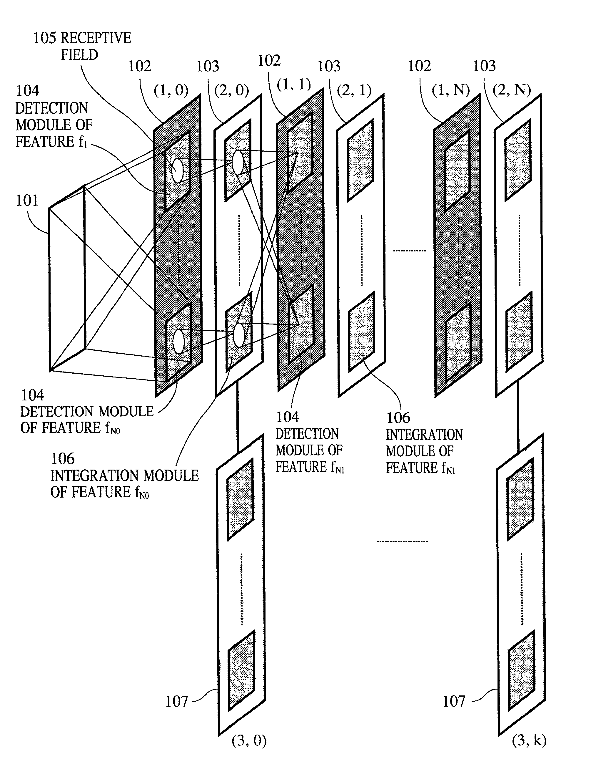
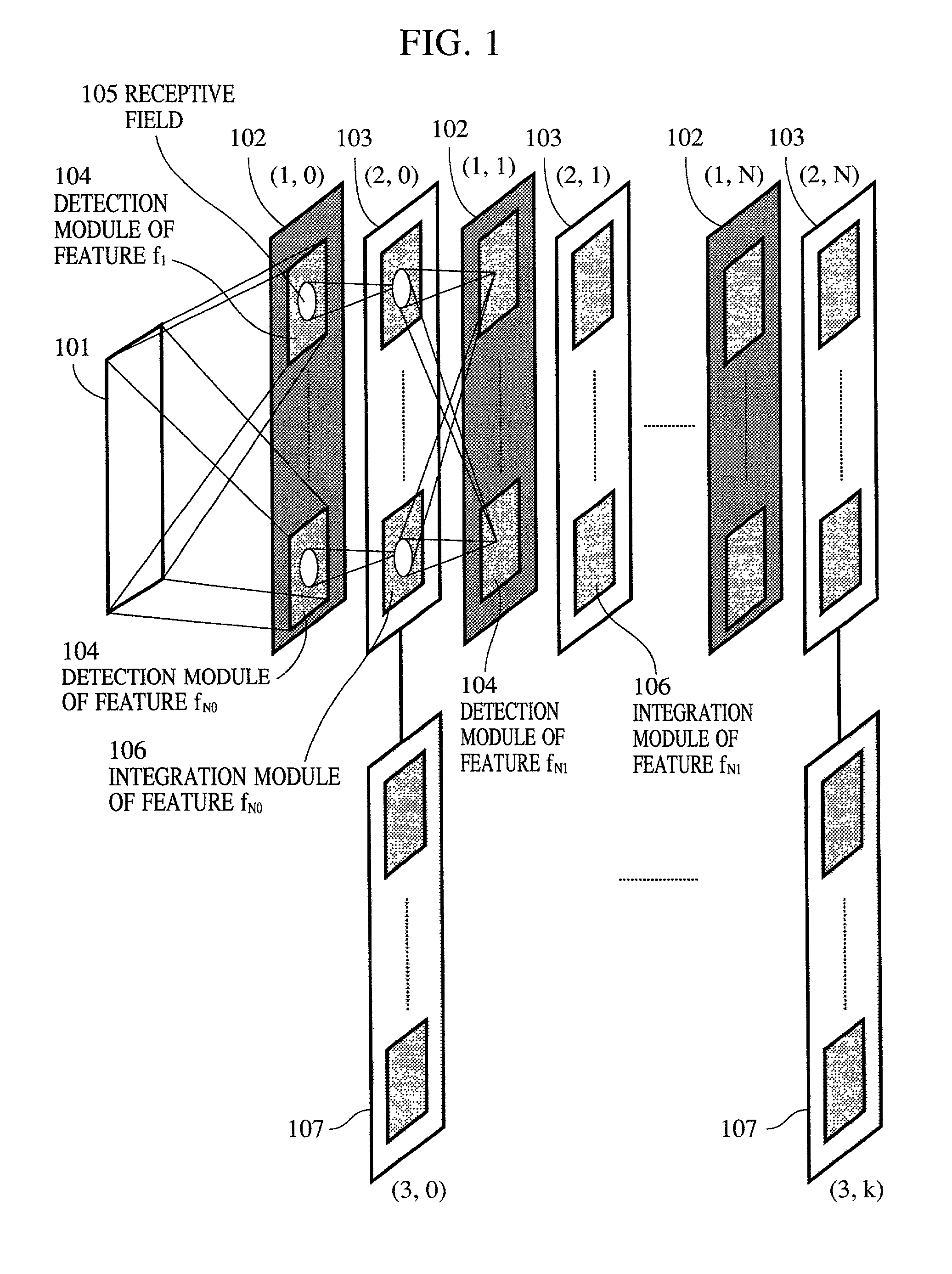
[0094]FIG. 1 shows a general construction of a pattern detecting or recognizing apparatus according to the embodiment. In this apparatus, pattern information is processed by a What pathway and a Where pathway. The What p...

second embodiment

[0216]In the first embodiment, synapses have been configured to carry out phase modulation. In this embodiment, the recognition of a graphic pattern or the like is performed using a network constituted by synapse elements that modulate pulse widths in analog values and integrate-and-fire neurons shown in the first embodiment in the network configuration shown in FIG. 1.

[0217]The modulation by a synapse is expressed by Wa=SijWb when the pulse width of a pre-synaptic signal is denoted as Wb, and the pulse width of a post-synaptic signal is denoted as Wa. In this case, Sij means the same as the connection strength in expression (5) of the first embodiment. To take a wide dynamic range for the modulation, the basic pulse width of a pulse signal must be set to a value that is sufficiently smaller than the period, i.e., a basic pulse interval.

[0218]A neuron fires or outputs a pulse when its potential exceeds a predetermined threshold value because of the charges accumulated due to the inf...

third embodiment

[0223]The feature detection neurons used in this embodiment are adapted to detect graphic features and their deformation on the basis of the time intervals in analog values and the orders of pulse arrivals, or detect graphic features on the basis of the levels of importance, which will be described hereinafter.

[0224]The network configuration used in this embodiment is the same as that shown in FIG. 1 except that a phase offset based on the location in a receptive field is imparted to each interlayer synaptic connection. FIG. 13 shows a sampling structure in the receptive field of a feature detection neuron employed in this embodiment. For example, if the receptive field is elliptical, as shown in FIG. 13, then the sampling structure is configured such that the phase modulation amounts at lattice points (S1, S2 . . . ) that are spirally sampled from the center position of the ellipse gradually increase. The phase modulation amount at an arbitrary point is defined as the phase modulat...


PUM


Abstract

A pattern detecting apparatus has a plurality of hierarchized neuron elements to detect a predetermined pattern included in input patterns. Pulse signals output from the plurality of neuron elements are given specific delays by synapse circuits associated with the individual elements. This makes it possible to transmit the pulse signals to the neuron elements of the succeeding layer through a common bus line so that they can be identified on a time base. The neuron elements of the succeeding layer output the pulse signals at output levels based on a arrival time pattern of the plurality of pulse signals received from the plurality of neuron elements of the preceding layer within a predetermined time window. Thus, the reliability of pattern detection can be improved, and the number of wires interconnecting the elements can be reduced by the use of the common bus line, leading to a small scale of circuit and reduced power consumption.

Description

BACKGROUND OF THE INVENTION[0001]1. Field of the Invention[0002]The present invention relates to an apparatus and a method mainly designed for recognizing a pattern or detecting a particular subject by using a parallel arithmetic device, such as a neural network.[0003]2. Description of the Related Art[0004]Hitherto, in the field of image recognition or speech recognition, the methods available for implementing such recognition have been roughly classified into two types. In one type, such recognition is implemented by performing serial arithmetic operation by employing, as a computer software program, a recognition processing algorithm tailored to a specific object to be recognized. In the other type, such recognition is implemented using a dedicated parallel image processor, such as a single instruction multiple data stream (SIMD) machine or a multiple instruction multiple data stream (MIMD) machine.[0005]The following will describe typical examples of image recognition algorithms....

Claims


Application Information

Patent Timeline
Patent Type & Authority Patents(United States)
IPC IPC(8): G06F17/00G06N5/02G06K9/00G06K9/46G06K9/66
CPCG06K9/4628G06K9/00973G06N3/049G06N3/063G06V10/94G06V10/454
Inventor MATSUGU, MASAKAZU
Owner CANON KK
Why Eureka
Try Eureka