Supercharge Your Innovation With Domain-Expert AI Agents!

Automatic mode detection circuits for configuring a terminal as an output terminal in a first mode as an input terminal in a second mode

a detection circuit and mode detection technology, applied in the field of electronic circuits, can solve the problems of conventional techniques, mode select signals generally increase the complexity of design and the number of factors, and achieve the effect of improving the number of factors and the complexity of design

Active Publication Date: 2006-05-30
CIRRUS LOGIC INC
View PDF5 Cites 6 Cited by
  • Summary
  • Abstract
  • Description
  • Claims
  • Application Information

AI Technical Summary

Benefits of technology

[0006]Embodiments of the inventive principles are useful in detecting the correct operating mode in any application in which a given circuit is capable of operating in multiple modes in response to alternate controlling signal sources. These controlling signals are provided from either on-chip or off-chip sources, in the case of an integrated circuit embodiment, and / or define the corresponding circuit or system as a system master or a system slave. For example, the present principles allow for the automatic detection of an incoming master clock when a circuit block is operating in a slave clock mode and for the detection of an incoming crystal output signal when that circuit block is operating in a master mode. The circuit may then be correctly configured to operate from the received master clock in the slave clock mode or to generate the master clock from the crystal output signal to drive other circuit blocks or devices in the master clock mode.

Problems solved by technology

This conventional technique, however, has a number of significant drawbacks.
Furthermore, mode select signals generally increase the complexity of the design and the number of factors, which must be considered at the system level.

Method used


Image

  • Automatic mode detection circuits for configuring a terminal as an output terminal in a first mode as an input terminal in a second mode
  • Automatic mode detection circuits for configuring a terminal as an output terminal in a first mode as an input terminal in a second mode
  • Automatic mode detection circuits for configuring a terminal as an output terminal in a first mode as an input terminal in a second mode

Examples


Embodiment Construction

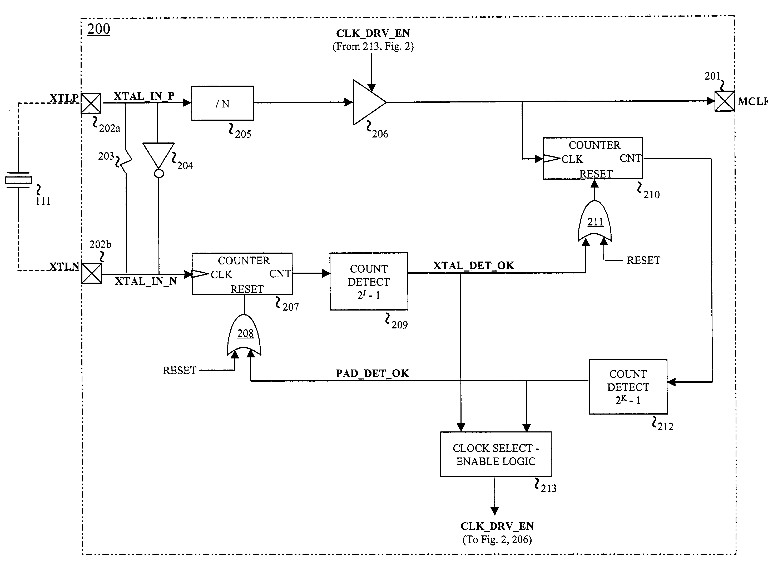
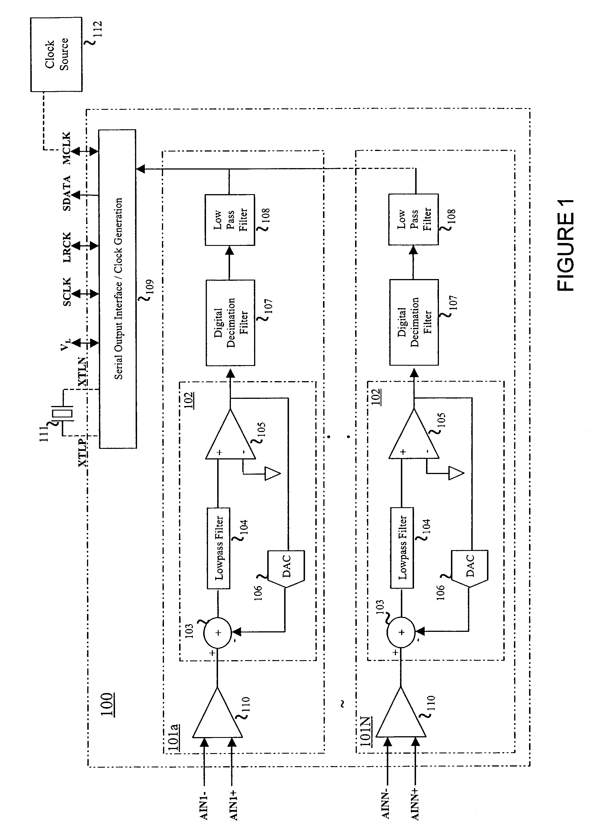
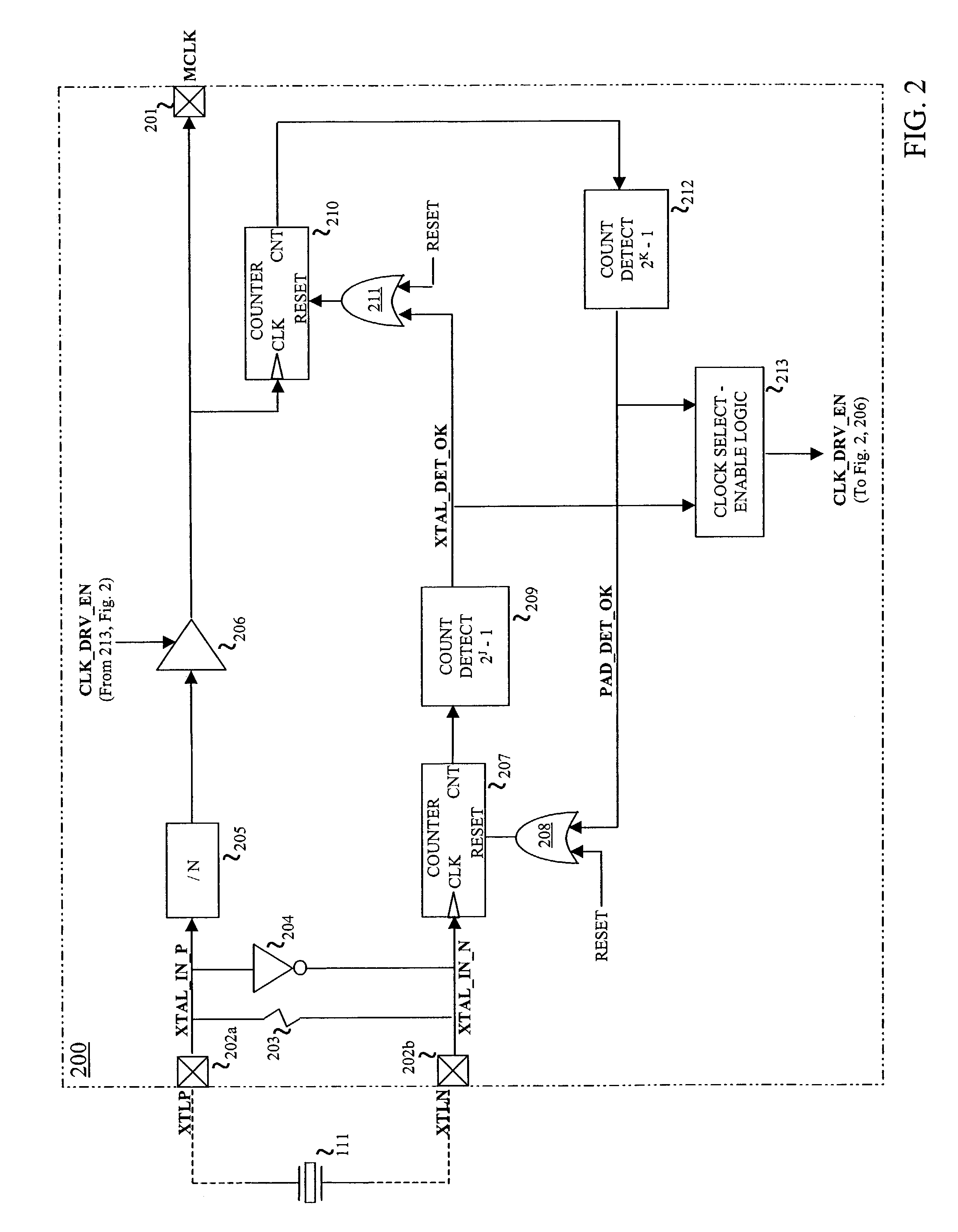
[0010]The principles of the present invention and their advantages are best understood by referring to the illustrated embodiment depicted in FIGS. 1–2 of the drawings, in which like numbers designate like parts.

[0011]FIG. 1 is a high-level block diagram of a single-chip audio analog-to-digital converter (ADC) 100 suitable for practicing the principles of the present invention. For illustrative purposes, ADC 100 is a delta-sigma ADC, although the present inventive principles are applicable to other types of ADCs, as well as digital-to-analog converter (DACs) and Codecs.

[0012]ADC 100 includes N conversion paths 101a . . . N, of which two paths 101a and 101N are shown for reference, for converting N channels of differential analog audio data respectively received at analog differential inputs AINN+ / −, where N is an integer of one (1) or greater. The analog inputs for each channel are passed through an input gain stage 110 and then a delta-sigma modulator 102.

[0013]Each delta-sigma mod...


PUM


Abstract

Mode detection circuitry includes first detection circuitry which detects the presence of a first input signal selectively presented at a first terminal for a first selected time duration and, in response, selectively generating a first control signal indicative of a first mode. Second detection circuitry detects the presence of a second input signal selectively presented at a second terminal for a second selected time duration and, in response, selectively generating a second control signal indicative of a second mode. Control circuitry configures the second terminal as an output terminal in the first mode and as an input terminal in the second mode in response to the first and second control signals.

Description

FIELD OF INVENTION[0001]The present invention relates in general to electronic circuits, and in particular, to automatic mode detection circuits and methods and systems utilizing the same.BACKGROUND OF INVENTION[0002]Often integrated circuit blocks are often capable of operating in multiple modes, such as multiple clocking modes, in order to support multiple system-level applications. Typically, when a circuit block operates in a slave clocking mode, a clock signal is input to the circuit block to synchronize its operations with the operations of associated circuit block in the system. During typical master-mode clock operations, a circuit block instead generates the clock signal required to synchronize the operations of a set of associated circuit blocks in the system. In other words, a circuit block operating in a slave-mode receives a controlling signal from another circuit block within the system while the circuit block operating in a master mode generates the controlling clock ...

Claims


Application Information

Patent Timeline
Patent Type & Authority Patents(United States)
IPC IPC(8): G06F1/30G01R31/28H01L25/00
CPCG06F1/04
Inventor GABORIAU, JOHANN G.FEI, XIAOFAN
Owner CIRRUS LOGIC INC
Features
  • R&D
  • Intellectual Property
  • Life Sciences
  • Materials
  • Tech Scout
  • Unparalleled Data Quality
  • Higher Quality Content
  • 60% Fewer Hallucinations
Learn More