Clip for heat sink

a heat sink and clip technology, applied in the field of clip for heat sinks, can solve the problems of inconvenient manual operation of the clip, unstable positioning of the heat sink on the cpu, and the inability to use the clip without the clamp, and achieve the effect of convenient manual operation

Inactive Publication Date: 2006-06-06
HON HAI PRECISION IND CO LTD
View PDF11 Cites 28 Cited by
  • Summary
  • Abstract
  • Description
  • Claims
  • Application Information

AI Technical Summary

Benefits of technology

[0010]Another object of the present invention is to provide a clip allowing easy manual operation thereof.
[0011]In order to achieve the objects set out above, a clip of the present invention for securing a heat sink comprises a pair of spaced V-shaped main bodies respectively received in grooves of the heat sink. A pair of spaced wings extends outwardly from opposite ends of each main body. The wings are slanted slightly upwardly. A hook is formed at a free end of each wing. Each hook has a V-shaped profile. The wings are wider than the hooks, for facilitating manual operation of the clip.

Problems solved by technology

Therefore manual operation of the clip is inconvenient.
Furthermore, the clip cannot be used without the clamp, because this results in unstable positioning of the heat sink on the CPU.
Thus installation of the clip is unduly complicated.

Method used


Image

  • Clip for heat sink
  • Clip for heat sink
  • Clip for heat sink

Examples


Embodiment Construction

[0017]Reference will now be made to the drawing figures to describe embodiments of the present invention in detail.

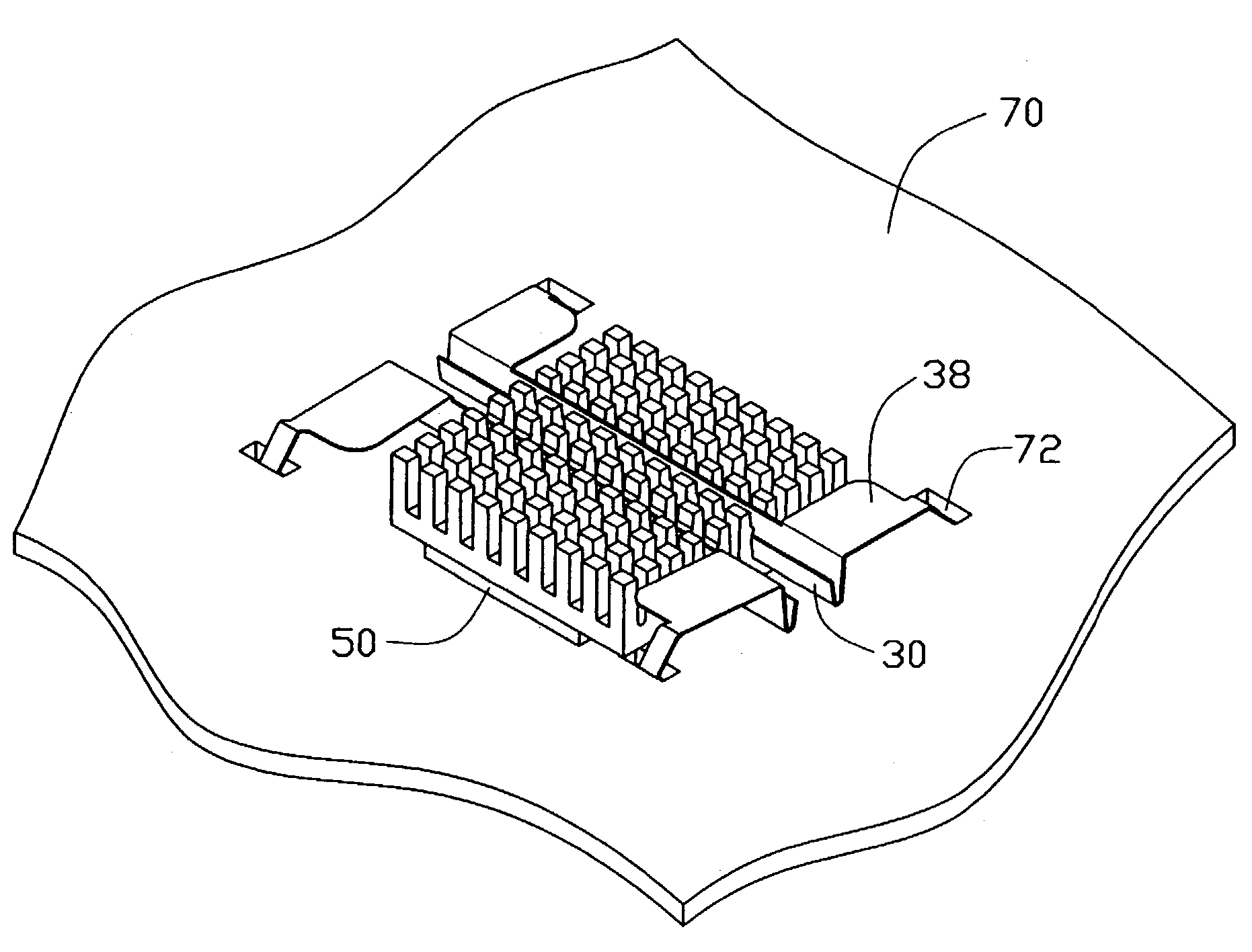
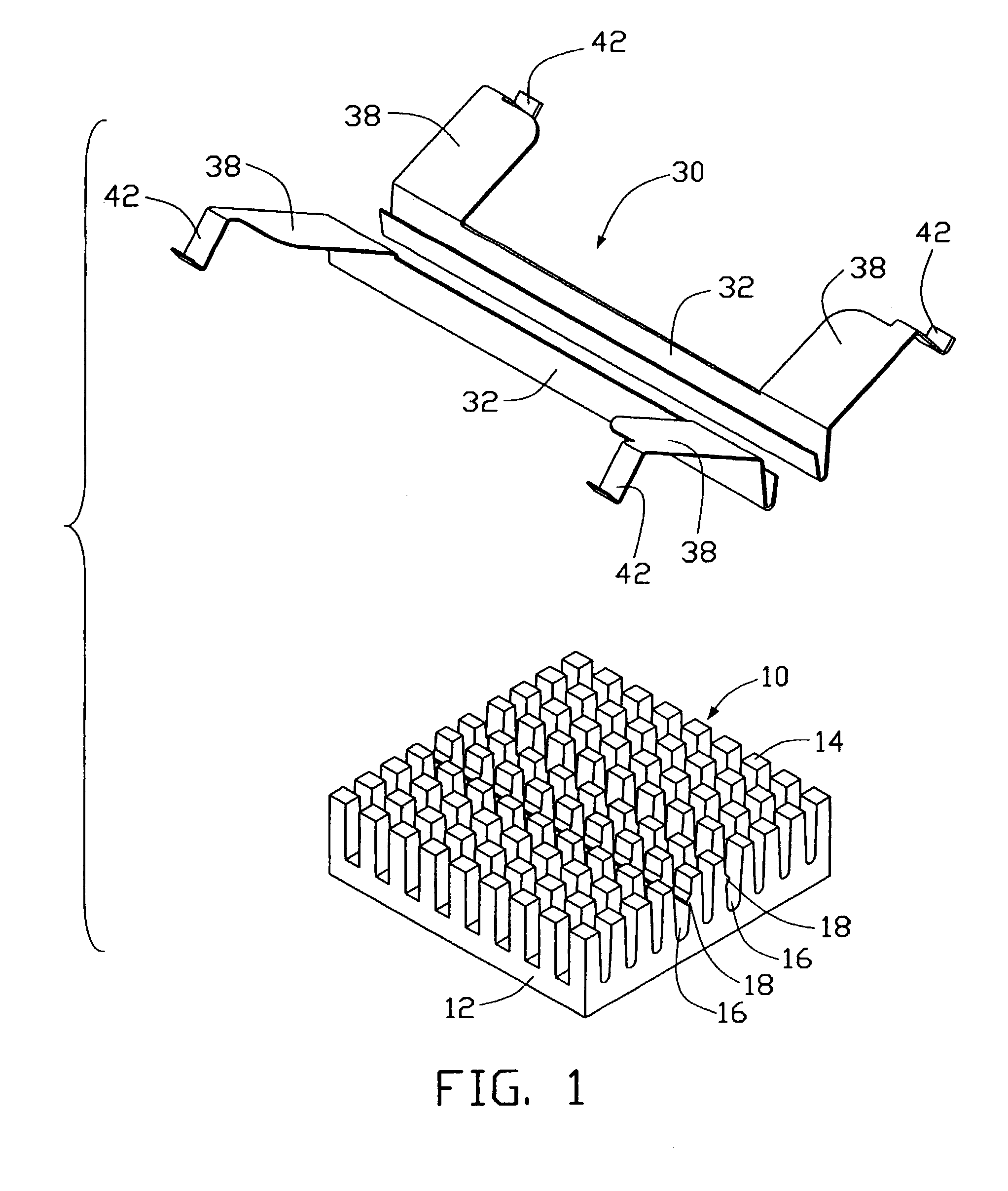
[0018]FIG. 1 shows a clip 30 in accordance with a preferred embodiment of the present invention, for securing a heat sink 10. Referring also to FIGS. 2-3, the heat sink 10 is mounted on an IC chip 50 that is supported on a printed circuit board (PCB) 70. The PCB 70 defines four through holes 72 therein. The through holes 72 surround the chip 50.

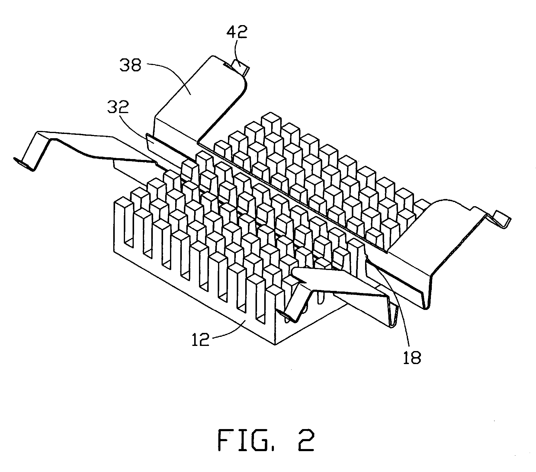
[0019]The heat sink 10 comprises a base 12 for mounting on the chip 50, and a plurality of fins 14 extending from a top surface of the base 12. The fins 14 are arrayed in parallel rows. Thus, a plurality of parallel grooves 16 is defined in the heat sink 10, each groove 16 being disposed between corresponding rows of the fins 14. Each groove 16 has a substantially V-shaped profile. A centermost groove 16 is disposed between two adjacent inmost rows of the fins 14. Each fin 14 in the two adjacent inmost rows of the fins 14 outward...


PUM


Abstract

A clip (30) securing a heat sink (10) includes a pair of spaced V-shaped main bodies (32) respectively received in grooves (16) of the heat sink. A pair of spaced wings (38) extends outwardly from opposite ends of each main body. The wings are slanted slightly upwardly. A hook (42) is formed at a free end of each wing. Each hook has a V-shaped profile. The wings are wider than the hooks, for facilitating manual operation of the clip.

Description

[0001]This is a divisional application of a copending application Ser. No. 10 / 042,562filed Dec. 10, 2001now abandoned.BACKGROUND OF THE INVENTION[0002]1. Field of the Invention[0003]The present invention relates to clips for heat sinks, and more particularly to a clip which firmly secures a heat sink to an integrated circuit (IC) chip.[0004]2. Description of Related Art[0005]A typical heat sink assembly used for a heat-generating device comprises a heat sink and an elongated clip separable from the heat sink. The heat-generating device may be an IC chip or a central processing unit (CPU). The clip is generally formed from a metal rod. The clip is placed in a groove of the heat sink, and is engaged with catches of a socket on which the heat-generating device is mounted. Thus the heat sink is secured to a top surface of the heat-generating device.[0006]A conventional clip is shown in Taiwan Patent Application No. 86209116. The clip is secured to a heat sink by positioning a central po...

Claims


Application Information

Patent Timeline
Patent Type & Authority Patents(United States)
IPC IPC(8): F28F7/00H01L23/34H01L23/40
CPCH01L23/4093H01L2924/0002H01L2924/00
Inventor LEE, HSIEH KUNLEE, DONYUN
Owner HON HAI PRECISION IND CO LTD
Why Eureka
Try Eureka