
Component for motor vehicles with airbag cover

a technology for motor vehicles and components, applied in vehicle safety arrangements, pedestrian/occupant safety arrangements, transportation and packaging, etc., can solve the problems that the damage of passengers cannot be completely prevented, and the deployment of airbags can be damaged in the area of the wing edges, so as to achieve the thinest possible form stability and the effect of stabilizing the layer

Inactive Publication Date: 2006-06-06
PEGUFORM
View PDF11 Cites 16 Cited by
  • Summary
  • Abstract
  • Description
  • Claims
  • Application Information

AI Technical Summary

Benefits of technology

[0005]Object of the invention is to provide a component of the afore-described type, which is characterized by a relatively simple and cost-efficient production method and which prevents injury of passengers and the risk of damage to the unfolding airbag in a vehicle which has been outfitted with the component.
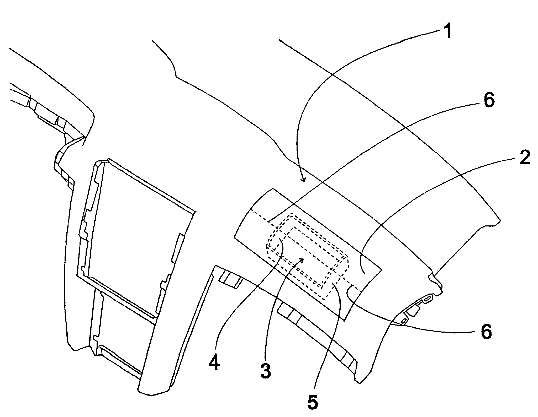
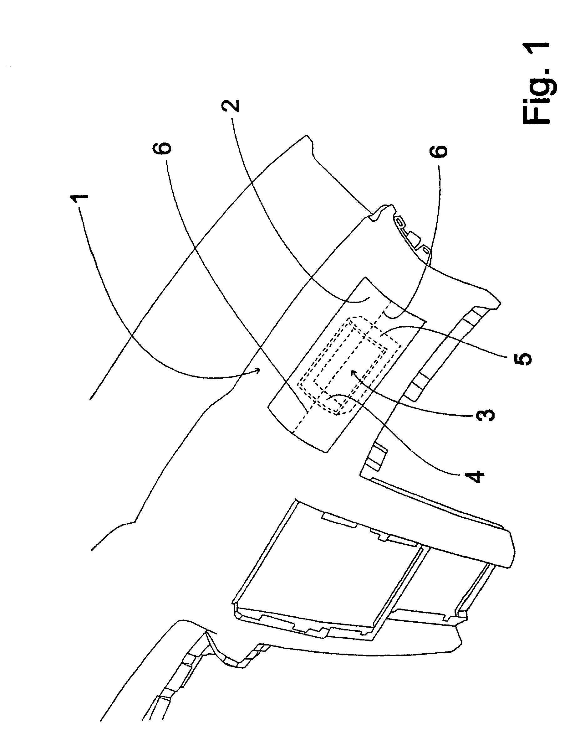
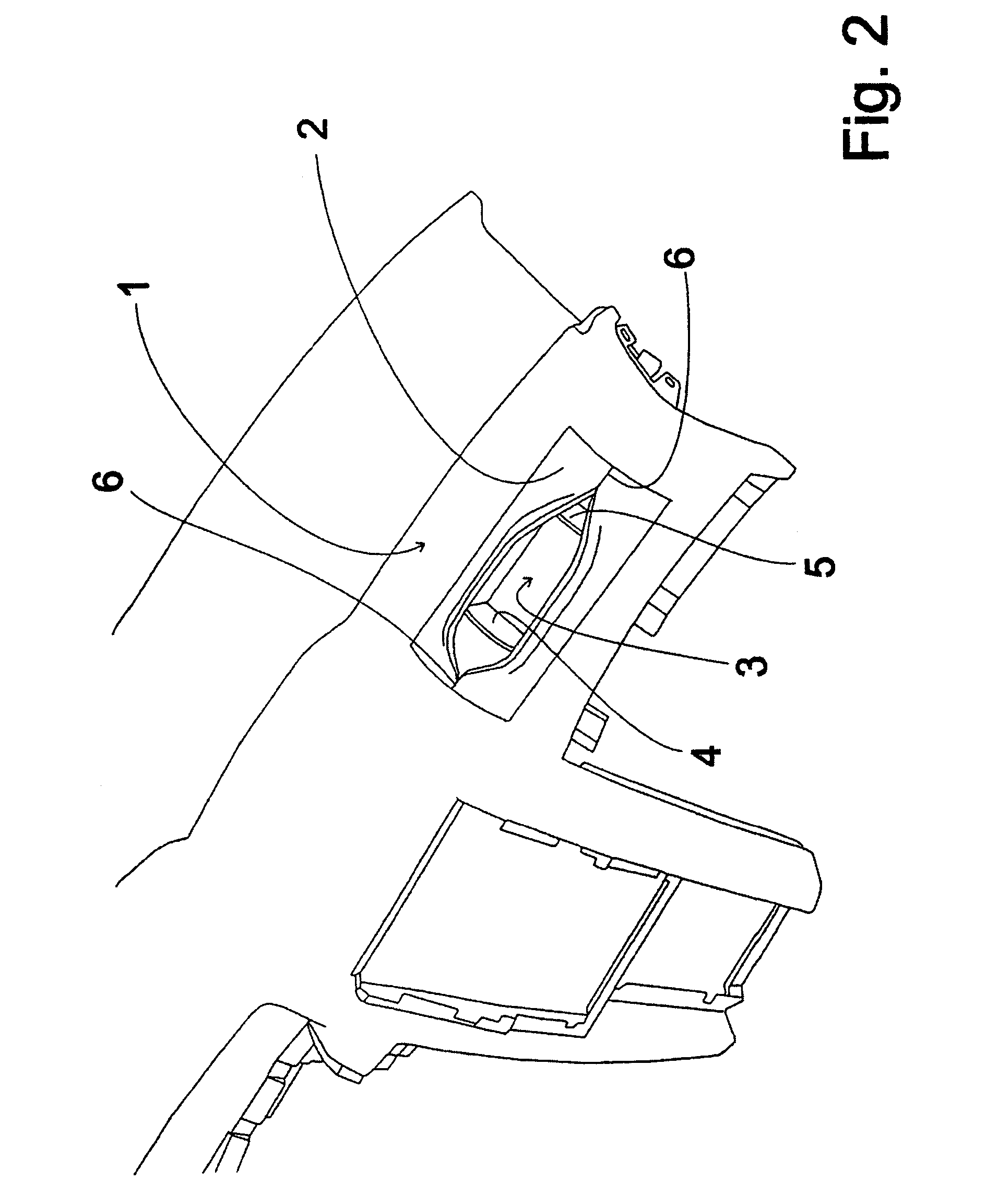
[0007]Since the airbag cover is made from elastic material, a certain flexibility is realized which, after opening of the weakened zones, allows a flexible yielding of the airbag cover upon emergence of the airbag from the deployment channel, without the risk of damage to the airbag. The normally considerable extension of the airbag cover beyond the opposite delimitations of the deployment channel and the weakened zones, in combination with the relatively high flexibility of the airbag cover, results in a type of expansion opening which can be likened to a fish mouth. The flexible areas on each side of the weakened zones yield under a certain widening due to the forces applied through the inflating airbag and due to this widening in the area of the weakened zones, clearance for the inflating airbag is realized.
[0008]In a practical development of the embodiment, the airbag cover is back-injected in the area of deployment of the component. As a result, an especially secure connection between the component and the airbag cover is realized with a relatively simple production.
[0011]In the latter embodiment, it is advantageous for a force decoupling around the areas of the weakened zones, to provide a decoupling recess between the side of the air bag cover facing the interior of the vehicle and the walls.
[0016]With regard to realizing highest possible form stability in the component, as a practical matter, a support of the component is formed with a relatively thin form stabilization layer in the area of deployment. The form stabilizing layer, for example, prevents caving-in of the deployment area, so that an airbag can be released essentially unimpaired under widening of the airbag cover along the weakened zones due to the form stabilizing layer being relatively thin.

Problems solved by technology

There is however the drawback that under certain circumstances the deploying airbag can be damaged in the area of the wing edges.
Furthermore, damage to the passengers cannot be completely precluded in case the wings completely separate upon deployment of the airbag.

Method used


Image

  • Component for motor vehicles with airbag cover
  • Component for motor vehicles with airbag cover
  • Component for motor vehicles with airbag cover

Examples


Embodiment Construction

[0023]FIG. 1 shows a perspective view of an instrument panel 1 as an embodiment of the component for motor vehicles according to the present invention. The instrument panel 1, which can also be produced from a hard plastic material, shows an airbag cover 2 of elastic plastic material. The airbag cover 2 is disposed in the area of the deployment channel 3, which serves as a receptacle of an airbag not shown in FIG. 1. The airbag cover 2 covers the deployment channel 3 and exhibits a single weakened zone 6 extending preferably centrically between opposite walls 4, 5, which delimit the deployment channel 3, and extending relatively far, for example about one half of each the distance of the walls 4, 5, beyond each of the walls 4, 5 that serve as a delimitation of the deployment channel. The weakened zone 6 is formed, for example, by providing a slot or a recess in the surface of the instrument panel 1 facing away from the interior of the vehicle.

[0024]FIG. 2 shows a perspective view of...


PUM


Abstract

The invention concerns a component (1) for motor vehicles, in particular, instrument panel, lateral covering or side member covering, comprising an airbag cover (2) arranged in the region of the filler channel (3) and having a weaker resistance zone opening when the airbag is inflated. The covering zone located on either side of the weaker resistance zone can move freely, from an extracted airbag, along a clearance path while remaining linked to the component 91), after the airbag has been inflated, in specific manner. The airbag cover (20) is an elastic material. The weakened resistance zone extends over the opposite delimitations (4, 5) of the filler channel 93), so as to ensure the extension and inflation of the airbag. Said device eliminates possible damage to the inflated airbag and injury risks incurred by passengers as result the burst parts projected coming from said cover.

Description

BACKGROUND OF THE INVENTION[0001]The invention relates to a component for a motor vehicle, in particular an instrument panel, side panel or support panel with an airbag cover, which is arranged in an deployment area associated with a deployment channel and which is provided with a weakened zone that will open upon release of an airbag, wherein areas of the airbag cover located on either side of the weakened zone are movable for clearing the deployment path of the releasing airbag and remain attached to the component after the airbag has inflated.[0002]A component of this type is known from EP 0583 079 A1. The afore-described component configured as an instrument panel shows an airbag cover which is arranged in the deployment channel and which is configured as a unitary piece with the instrument panel, which is of a rigid foam material. A weakened zone in the airbag cover is formed through a material reduction which, upon deployment of the airbag, breaks open under formation of two w...

Claims


Application Information

Patent Timeline
IPC IPC(8): B60R21/20B60R21/16B60R21/2165
CPCB60R21/2165B60R2021/161
Inventor FREYSTEDT, BERND
Owner PEGUFORM
Learn More