
Grounding stud

a grounding stud and electrical connection technology, applied in the direction of connection contact material, electrical apparatus casing/cabinet/drawer, coupling device connection, etc., can solve the problems of insufficient cross sectional area of electrical conductivity, add extra cost and complexity to eyelet and installation process, etc., to increase the automatic alignment of eyelets, increase the electrical cross sectional area, and maximize the electrical contact area

Inactive Publication Date: 2006-06-06
NEWFREY
View PDF65 Cites 45 Cited by
  • Summary
  • Abstract
  • Description
  • Claims
  • Application Information

AI Technical Summary

Benefits of technology

[0005]In accordance with the present invention, a preferred embodiment of an electrical connection employs a stud having a patterned segment, a shoulder and a flange. In another aspect of the present invention, the shoulder has seven or more predominantly flat faces. In a further aspect of the present invention, the shoulder has an octagonal cross sectional shape. Still another aspect of the present invention provides a nut which is threadably engaged with the patterned segment of the stud and an eyelet secured between the nut and the flange of the stud. Yet another aspect of the present invention allows the stud to be welded onto an automotive body panel or the like for use as a grounding stud.

Problems solved by technology

This hexagonal shoulder configuration, however, provides undesirably large corner-to-corner and flat-to-flat dimensions across the shoulder in order to fit within standard stud welding machinery which can only handle a certain maximum outside diameter of stud; thus, the hexagonal shoulder leads to insufficient cross sectional area for electrical conductivity.
This adds extra cost and complexity to the eyelet and installation process.

Method used


Image

  • Grounding stud
  • Grounding stud
  • Grounding stud

Examples


Embodiment Construction

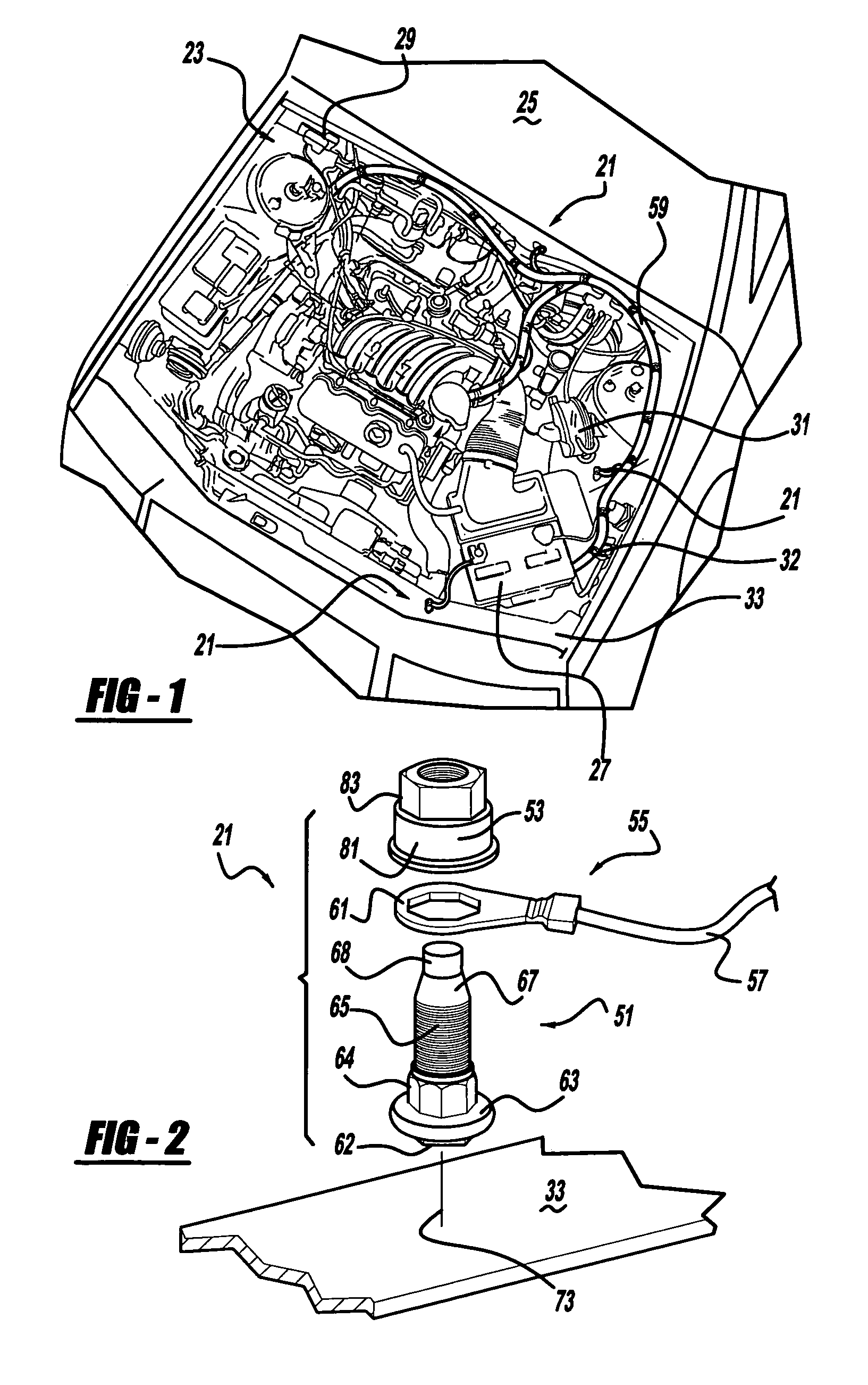
[0015]FIG. 1 shows a stud electrical connection 21 of the present invention employed in an engine compartment 23 of an automotive vehicle 25. Stud electrical connection 21 is operable to conduct electricity from an electrical component, such as a battery 27, direct current window wiper motor 29, horn 31, power distribution box 32 or the like, to a conductive metal panel or frame 33 of the vehicle.

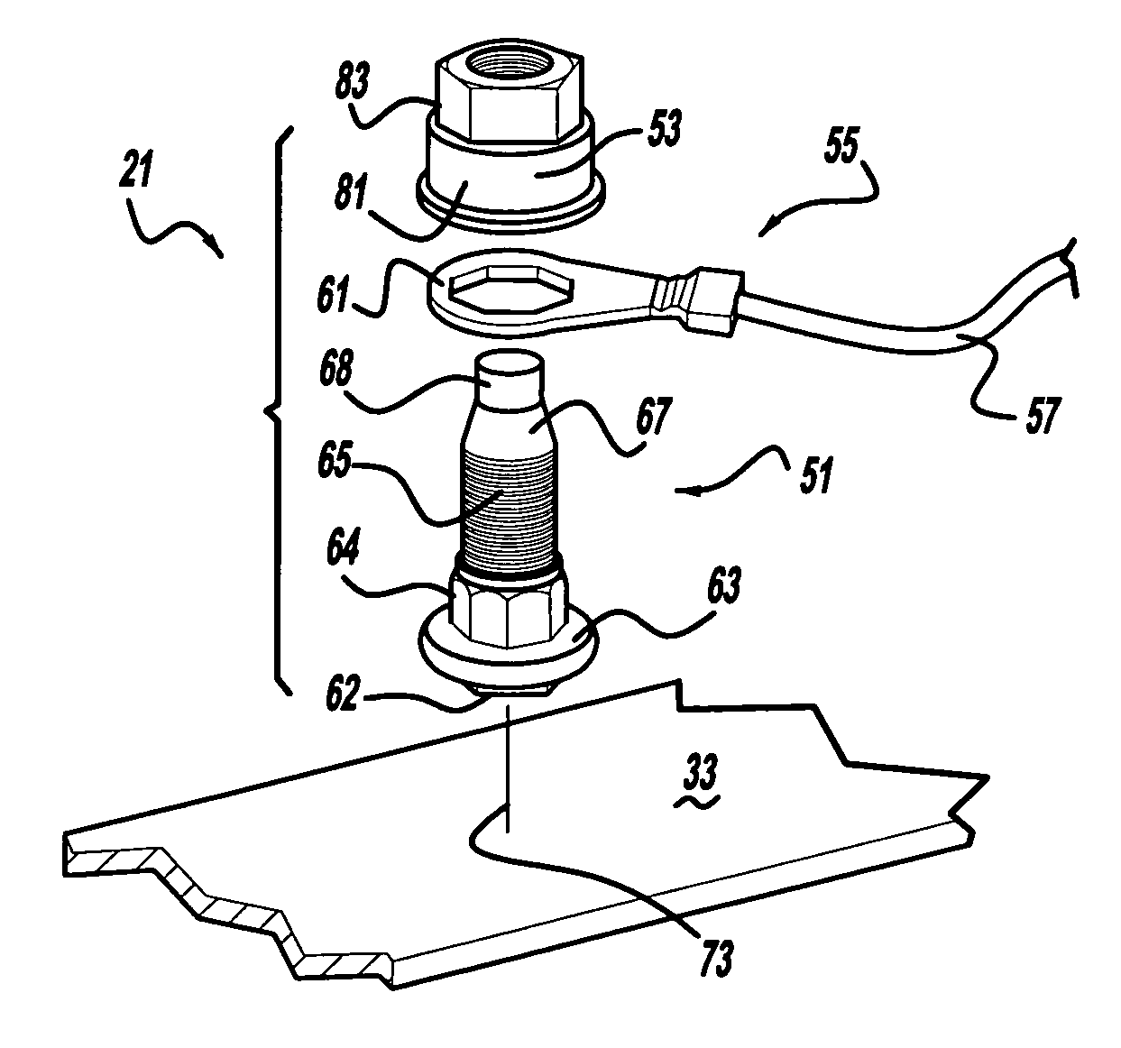
[0016]Referring to FIGS. 2–7, the preferred embodiment of stud electrical connection 21 includes a grounding weld stud 51, a nut 53, and a female electrical connector 55. Electrical connector 55 includes a wire 57, branching from a wire harness 59 (see FIG. 1), with a stamped metal eyelet 61 crimped onto an end thereof. Wire 57 is made of a flexible copper inner wire surrounded by an insulative casing.

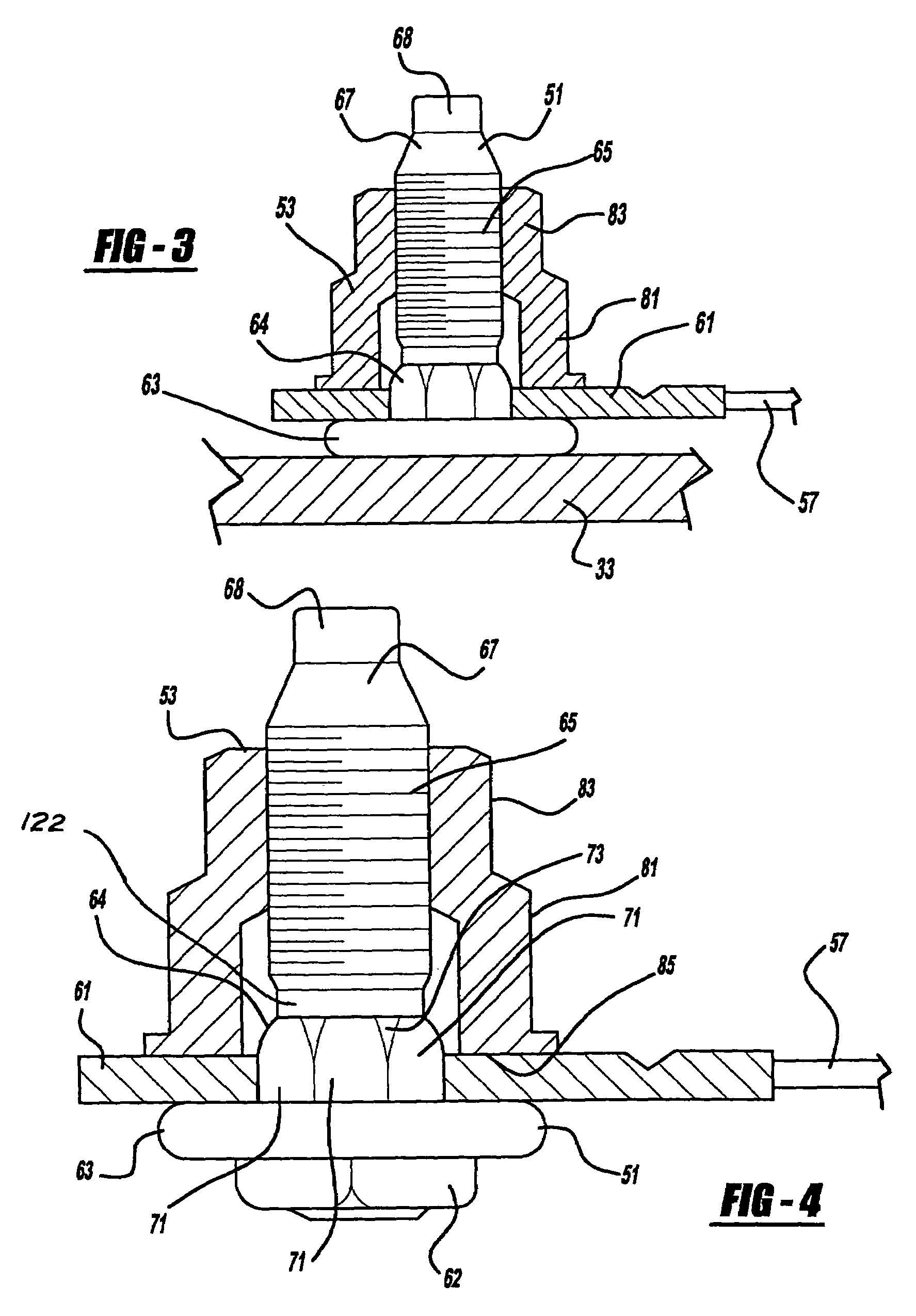
[0017]Stud 51 includes a securing segment 62, a flange 63, a shoulder 64, a patterned segment 65, an inwardly tapered segment 67 and an anti-cross threading lead-in end segment 68. Securing se...


PUM


Abstract

A preferred embodiment of an electrical connection employs a stud having a patterned segment, a shoulder and a flange. In another aspect of the present invention, the shoulder has seven or more predominantly flat faces. In a further aspect of the present invention, the shoulder has an octagonal cross sectional shape.

Description

CROSS REFERENCE TO RELATED APPLICATIONS[0001]This application is a continuation-in-part of U.S. Ser. No. 10 / 075,090, filed Feb. 12, 2002 now U.S. Pat. No. 6,746,285, which claims priority to U.S. Provisional Ser. No. 60 / 270,084, filed Feb. 20, 2001, both of which are incorporated by reference herein.BACKGROUND OF THE INVENTION[0002]This invention relates generally to an electrical connection and more specifically to an electrical connection for an automotive vehicle employing a grounding stud.[0003]It is common to arc weld an elongated circular end of a threaded metal stud onto a sheet metal body panel of an automotive vehicle. Various parts are then inserted upon the single threaded stud and an internally threaded nut is rotationally inserted onto the stud. Conventional threaded weld studs have also been employed as electrical grounding points for a vehicle wire harness to an engine compartment frame or body panel. It is also known to employ a grounding weld stud that has a threade...

Claims


Application Information

Patent Timeline
IPC IPC(8): H01R4/38H01R4/30H01R4/64H01R11/12H01R12/00
CPCH01R4/30H01R11/12H01R4/64H01R2201/26
Inventor DELCOURT, MARK H.GOUIN, THOMAS
Owner NEWFREY
Features
  • Generate Ideas
  • Intellectual Property
  • Life Sciences
  • Materials
  • Tech Scout
  • Unparalleled Data Quality
  • Higher Quality Content
  • 60% Fewer Hallucinations
Learn More