
Vehicle wash apparatus with an adjustable boom

Inactive Publication Date: 2006-06-06
MARK VII EQUIP
View PDF74 Cites 69 Cited by
  • Summary
  • Abstract
  • Description
  • Claims
  • Application Information

AI Technical Summary

Benefits of technology

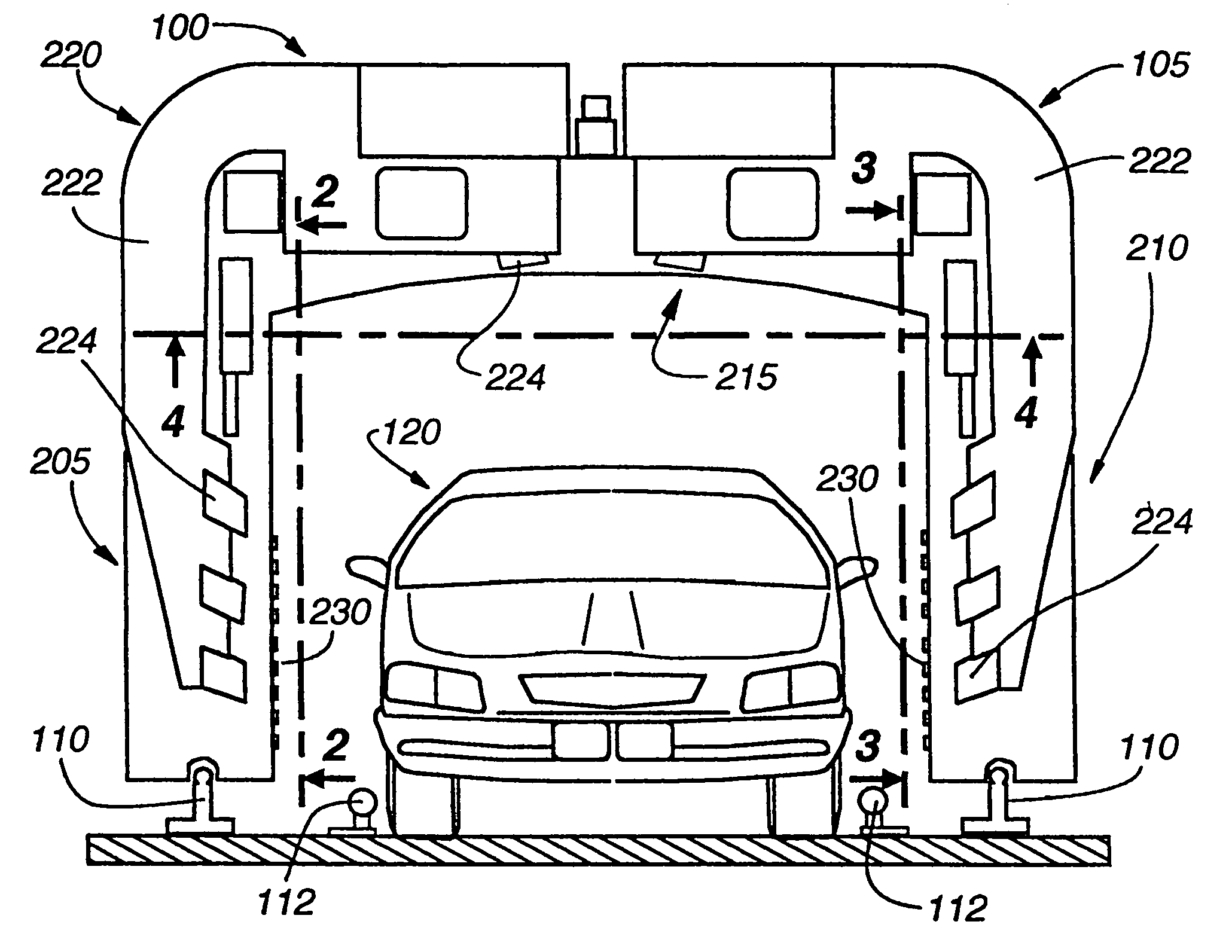
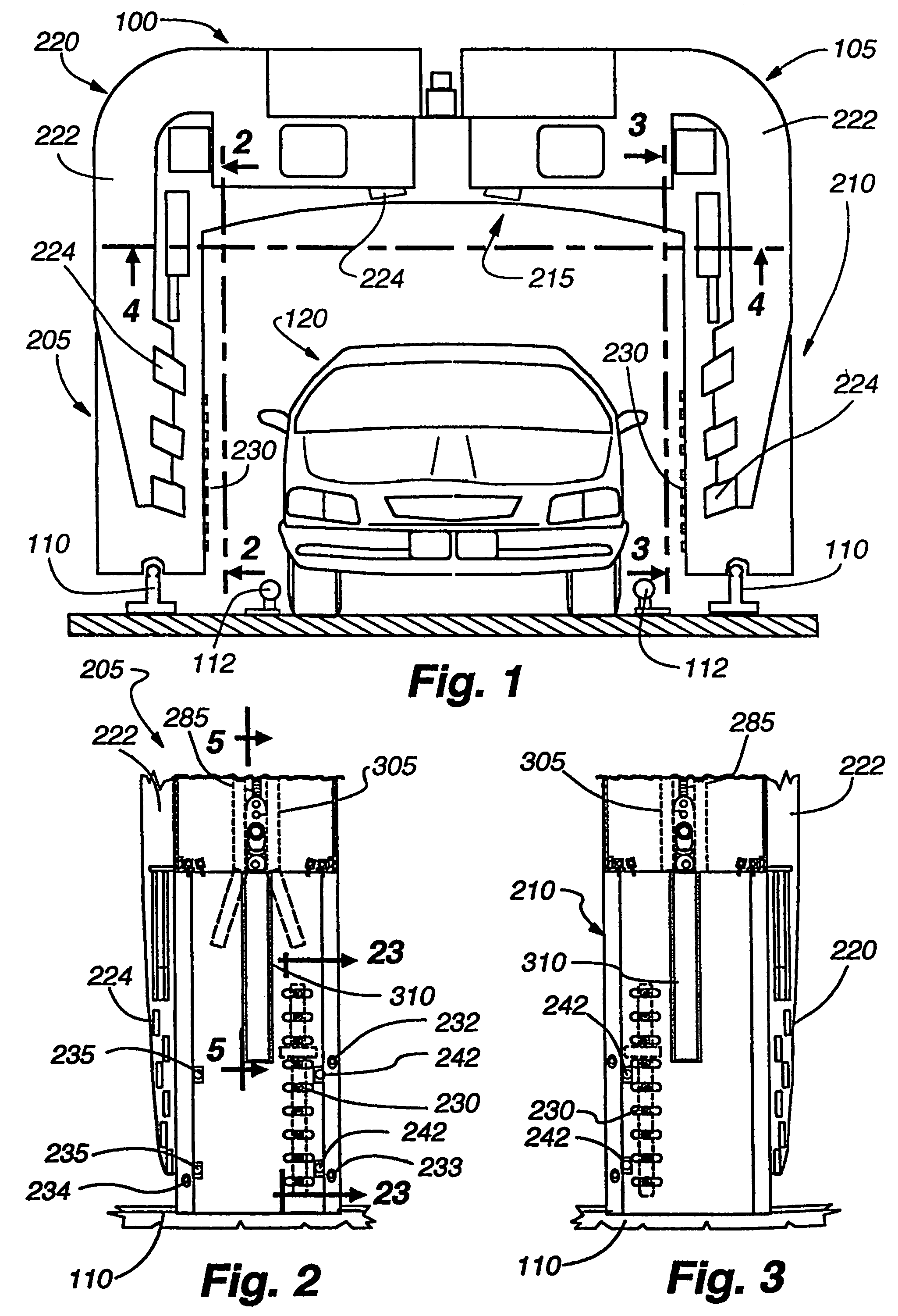
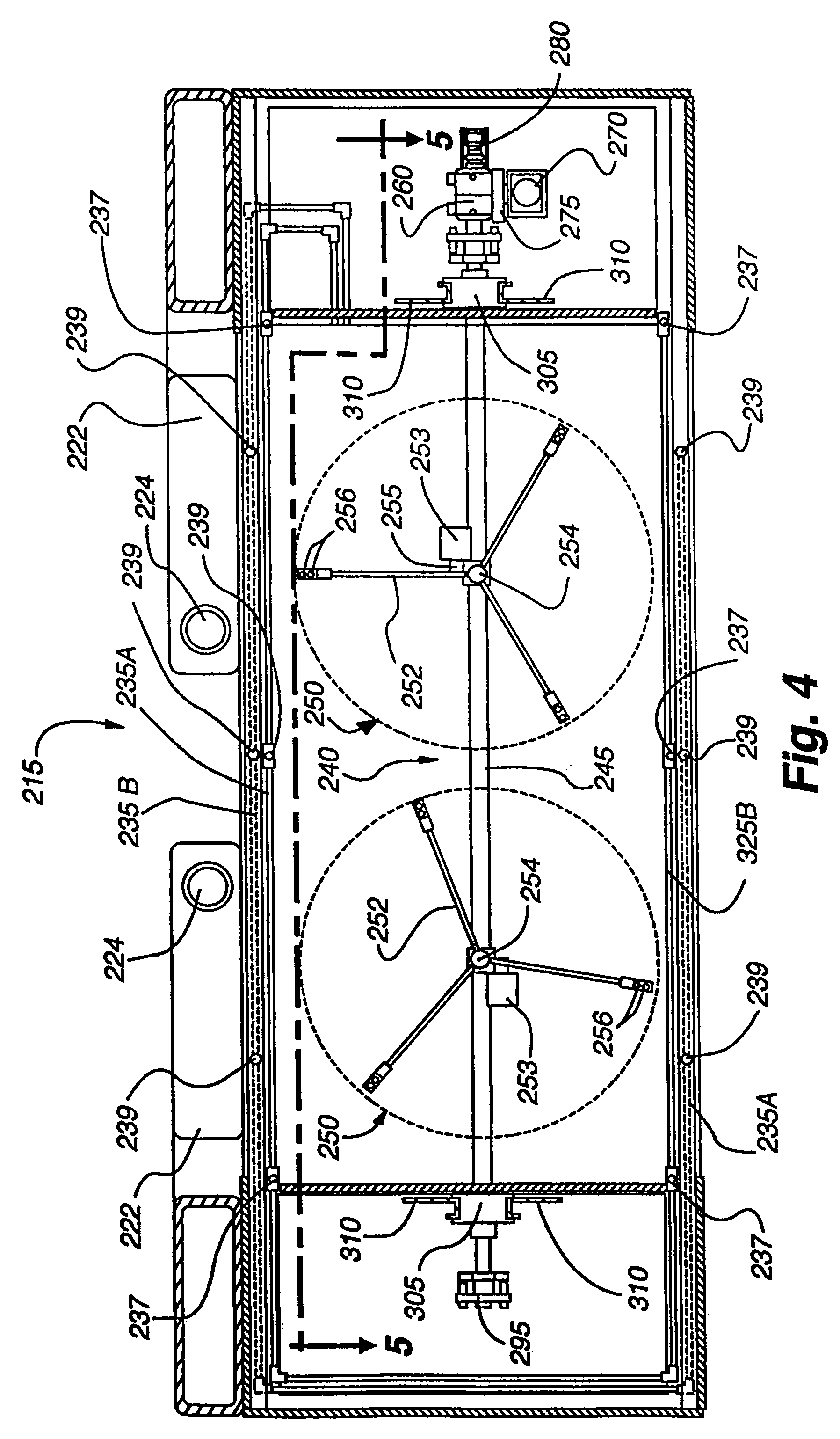
[0012]In the preferred embodiment, one or more low pressure fluid conduits with low pressure nozzles attached thereto are attached to a bottom surface of the horizontal span of the gantry, wherein specialty fluids such as clear coats and spot free rinses may be sprayed on the top of the vehicle. Additionally, low-pressure fluid conduits may be provided on either leg of the gantry to spray the fluids onto the side of the vehicle. By providing a low-pressure conduit for each specialty fluid, the conduits need not be flushed to change fluids. Furthermore, by utilizing specialized individual conduits, specialty fluid efficiency is enhanced. The overhead and side locations of the conduits ensures accurate and adequate application of fluid to all surfaces of the vehicle. In one embodiment, clear coat (or drying agent) conduits are located proximate either the front or rear face of the gantry and spot free rinse (or soft water) conduits are located proximate the other of the front or rear face of the gantry, wherein both specialty solutions can be applied in a single pass of the gantry over the vehicle.

Problems solved by technology

As the distance between the nozzle and the adjacent surface increases, the speed of the cleaning fluid decreases; also the jet begins to fan increasing the impact area on the adjacent surface, thereby spreading the impact force over a greater area, and reducing cleaning effectiveness.
Accordingly, those parts of a vehicle that are furthest from the nozzles may not be adequately cleaned.
Typically, gantry-type cleaning systems have the most difficulty cleaning the front and rear of a vehicle, since the nozzles located at the sides and top of the gantry normally direct jets of cleaning fluid parallel or at a very shallow angle to the vehicle's front and rear surfaces.
Both of these solutions are relatively expensive when compared to the other liquids used during the wash cycle such as water.
This is undesirable for at least two reasons: one, the specialty solution left in the supply lines must be purged prior to the beginning of the next vehicle wash; and two, the use of a high pressure delivery device might deliver a greater than necessary volume of specialty solution to the vehicle as the gantry traverses the vehicle's length.
The result is an inefficient use of the expensive specialty solutions.
Unfortunately, these vertically mounted delivery systems have difficulty in delivering solution in a manner that completely covers the top surfaces of a vehicle as there is often little impetus for the applied specialty solution to flow along the horizontal top surfaces of the vehicle, especially when the solution is in the form of a foam.

Method used


Image

  • Vehicle wash apparatus with an adjustable boom
  • Vehicle wash apparatus with an adjustable boom
  • Vehicle wash apparatus with an adjustable boom

Examples


first alternative embodiment

A First Alternative Embodiment

[0083]With reference to FIG. 17, the reciprocating wand assembly 400 of a first alternative embodiment is shown mounted on the pivoting boom 245 which has been adapted to serve as a high pressure fluid delivery manifold as well. The pivoting boom 245 is connected to a supply (not shown) of pressurized liquid to be sprayed onto the vehicle and supports three equally spaced reciprocating wands 410 through vertical hollow pivot shafts 420 associated with each wand 410. The shafts 420 are mounted on appropriate bearings 425 that allow the wands to reciprocate in a horizontal plane through their operative connection with a drive / link system 415. Each hollow pivot shaft is in fluid communication in a conventional manner with the interior of the pivoting boom 245 so that liquid within the manifold boom can pass from the manifold into the interior of the hollow pivot shaft. Each pivot shaft is, in turn, in fluid communication with the interior of each wand 410,...

second alternative embodiment

A Second Alternative Embodiment

[0091]FIGS. 29–32 illustrate a second alternative embodiment, wherein oscillating or turbo nozzles 705 are attached directly to parallel and spaced boom tubes 710. The cleaning action of the turbo and / or oscillating nozzles 705 ensures complete coverage of the underlying vehicle surface without the utilization of rotating or pivoting wand assemblies. As shown, the boom tubes 710 also double as fluid delivery conduits to carry the high pressure cleaning fluid to the nozzles 705. Preferably, cleaning solution can be routed to either one of the tubes 710 independently of the other, whereby one bank of nozzles attached to one tube can be turned off while the bank of nozzles are turned on. The nozzles may be orientated in a variety of angles relative to the boom tubes 710 depending on the spray pattern of the chosen nozzles. Typically, the boom tubes 710 will be spaced apart from each other a distance of around 18 inches, which has found to be effective in ...

third alternative embodiment

A Third Alternative Embodiment

[0092]A third alternative embodiment is illustrated in FIGS. 19 and 20, wherein the tilt of the pivoting boom 245 is directly dependent on the vertical position of the moveable platform 240. Although this system does not offer the same degree of customizability for vehicles of differing profiles, it less complicated than the preferred embodiment and potentially much less expensive to produce as well. In the third alternative embodiment, a follower arm 505 is keyed to the pivoting boom 245. The follower arm 505 is typically an elongated member that is vertically orientated along its length. The follower arm 505 is attached at an upper end to the pivoting boom 245. The follower arm 505 rides between two opposing guides surfaces 515 formed by framework 510 within the left leg 205 of the gantry structure 105. Near the top of the left leg 205 the wand assemblies 250 are preferably orientated parallel to the ground. Accordingly, the opposing guide surfaces 51...


PUM


Abstract

An automatic vehicle washing system is described. The vehicle washing system incorporates an elongated overhead cleaning platform for cleaning the front, top and rear surfaces of a vehicle. The overhead cleaning platform is attached to a single lift mechanism at a first end and is suspended from a belt at a second end, wherein the belt is also operatively connected to the first end. Accordingly, vertical movement of the lift actuator causes both ends of the platform to uniformly rise or descend. The platform further comprises a pivotal boom with fluid nozzles attached thereto, and a reciprocating pivotal actuator. The reciprocating pivotal actuator is capable of pivotal movement to any number of angular orientations within its operative range of motion. Advantageously, the pivotal and vertical positions of the nozzles can be independently varied, permitting the location of the overhead cleaning nozzles to be optimized for various vehicle profiles.

Description

CROSS-REFERENCE TO RELATED APPLICATION[0001]This application is a divisional of U.S. application Ser. No. 09 / 849,763, filed May 4, 2001, and is hereby incorporated by reference as if fully disclosed herein.FIELD OF THE INVENTION[0002]The present invention relates generally to automatic vehicle washing systems and, more particularly, to an overhead cleaning platform capable of independent vertical and pivotal positioning of a plurality of nozzles attached thereto.BACKGROUND OF THE INVENTION[0003]“Brushless” automated vehicle washing systems are commonly utilized to quickly and efficiently clean vehicles without requiring any hand scrubbing or contact between cleaning members and the exterior of a vehicle. Brushless vehicle washing systems utilize jets of pressurized cleaning fluid sprayed from a plurality of nozzles to wash away dirt and grime from the exterior surfaces of a vehicle. In one common type of washing system, the nozzles are commonly arranged in a gantry. The gantry eithe...

Claims


Application Information

Patent Timeline
IPC IPC(8): B08B3/02B60S3/04
CPCB60S3/04
Inventor FRATELLO, DANIEL A.JOHNSON, JAMESMINGEE, MICHAEL W.LEPPO, JONGAUTHIER, DAVID M.ENGEN, ERICMCCADDEN, DENNISTRAN, THANH J.
Owner MARK VII EQUIP
Learn More