3D fiber elements with high moment of inertia characteristics in composite sandwich laminates

a composite sandwich and fiber element technology, applied in the field of composite sandwich structure, can solve the problems of insufficient fiber composite structure for larger sandwich thickness applications requiring flexural stiffness and shear stiffness, modulus decrease, excessive shear deflection, etc., and achieve the effect of increasing shear modulus and high moment of inertia

Inactive Publication Date: 2006-06-06
EBERT COMPOSITES
View PDF127 Cites 17 Cited by
  • Summary
  • Abstract
  • Description
  • Claims
  • Application Information

AI Technical Summary

Benefits of technology

[0026]The present invention increases shear modulus in 3-D Z-axis fiber-reinforced composite laminate structures, especially in the core, by creating high moment-of-inertia solid composite internal panels made of contiguous cured resin Z-axis fiber bundles in the Z-Y and Z-X directions.

Problems solved by technology

Also, the shear modulus decreases as the sandwich thickness increases, making the shear deflections excessive and the fiber composite structure inadequate for larger sandwich thickness applications requiring flexural stiffness and shear stiffness.

Method used


Image

  • 3D fiber elements with high moment of inertia characteristics in composite sandwich laminates
  • 3D fiber elements with high moment of inertia characteristics in composite sandwich laminates
  • 3D fiber elements with high moment of inertia characteristics in composite sandwich laminates

Examples


Embodiment Construction

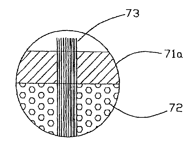
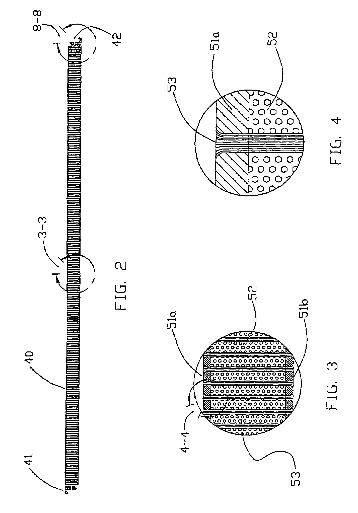
[0042]With reference generally to FIGS. 1–12, a Z-axis fiber-reinforced composite laminate structure 140 with high moment-of-inertia cured resin fiber structural elements 142 will be described. Before describing the Z-axis fiber-reinforced composite laminate structure 140 and high moment-of-inertia cured resin Z-axis fiber structural elements 142, a method and application for forming a pultruded and clinched 3-D Z-axis fiber-reinforced composite laminate structure will be described.

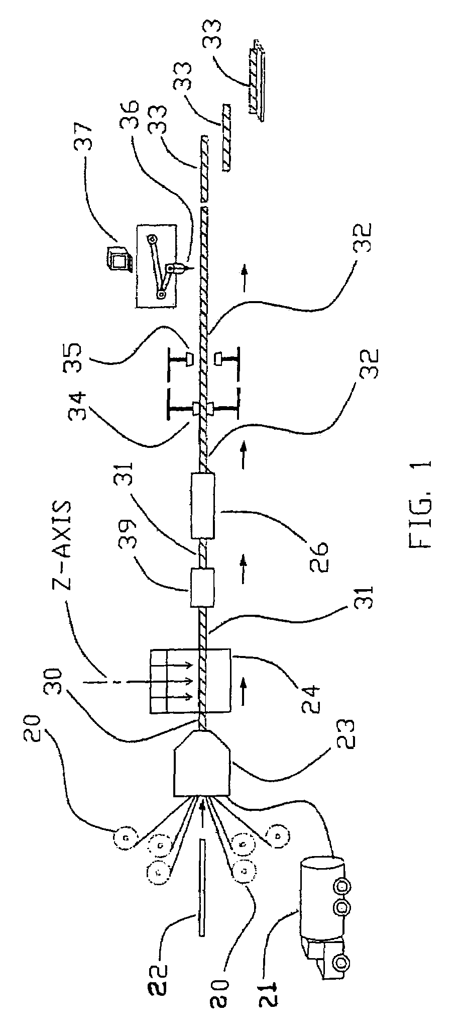
[0043]FIG. 1 illustrates a method and application for forming a pultruded and clinched 3-D Z-axis fiber reinforced composite laminate structure. The pultrusion direction is from left-to-right in FIG. 1 as shown by the arrows. The key components of the apparatus will become evident through the following description.

[0044]Shown in FIG. 1 are the grippers 34 and 35. These are typically hydraulically actuated devices that can grip a completely cured composite laminate panel 32 as it exits pultrusion die 26. T...


PUM

PropertyMeasurementUnit
shear modulusaaaaaaaaaa
thicknessaaaaaaaaaa
widthaaaaaaaaaa

Abstract

A shear-resistant Z-axis fiber-reinforced composite laminate structure includes a core material; an upper laminate; a lower laminate; and a plurality of contiguous cured resin Z-axis fiber bundles disposed in the core material between the upper laminate and the lower laminate to form high moment-of-inertia solid composite structural elements in the core material.

Description

REFERENCE TO RELATED APPLICATION[0001]This application is a continuation-in-part of U.S. patent application Ser. No. 10 / 744,630 filed Dec. 23, 2003, which is a continuation of U.S. patent application Ser. No. 10 / 059,956, U.S. Pat. No. 6,676,785, filed Nov. 19, 2001, which claims the benefit of provisional patent application 60 / 298,523 filed on Jun. 15, 2001; provisional patent application 60 / 281,838 filed on Apr. 6, 2001; and provisional patent application 60 / 293,939 filed on May 29, 2001 under 35 U.S.C. 119(e). This application also claims the benefit of prior provisional patent application 60 / 477,445 filed on Jun. 9, 2003 under 35 U.S.C. 119(e).FIELD OF THE INVENTION[0002]The present invention relates, in general, to composite laminate structures, and, in particular to composite laminate structures and Z-axis fiber elements in composite laminate structures with high shear modulus.BACKGROUND OF THE INVENTION[0003]U.S. Pat. Nos. 6,645,333 and 6,676,785, which are hereby incorporated...

Claims


Application Information

Patent Timeline
Patent Type & Authority Patents(United States)
IPC IPC(8): B32B5/14B29C70/08B29C70/24B29C70/50B29C70/76B32BB32B5/02E01C9/08E04C2/296
CPCB29C70/086B29C70/088B29C70/24B29C70/50B29C70/763E01C9/086E04C2/296B32B5/02Y10T428/24174Y10T428/24116Y10T428/233Y10T428/23914Y10T428/249924Y10T428/24996Y10T428/249986B32B2038/0076B32B2260/021B32B2260/046B32B2305/08B32B2307/542
Inventor JOHNSON, DAVID W.
Owner EBERT COMPOSITES
Why Eureka
Try Eureka