Linear motor, and secondary for a linear motor

a linear motor and motor secondary technology, applied in the field of linear motors, can solve the problems of disadvantage, material theft, and other regions that can be damaged fairly easily, and achieve the effect of sufficient firmness and accurate measurement of position

Inactive Publication Date: 2006-06-06
SIEMENS AG
View PDF8 Cites 17 Cited by
  • Summary
  • Abstract
  • Description
  • Claims
  • Application Information

AI Technical Summary

Benefits of technology

[0012]The present invention resolves prior art problems by providing an anti-skid layer for increasing the friction between the secondary and the cover. In this way, the initial breakaway torque, required to displace the cover, can be increased in a simple manner. The cover rests on a surface of the secondary member and adheres thereto because, for example, the magnetizable material of the cover is attracted by the permanent magnets of the secondary.
[0013]Suitably, the anti-skid layer adheres permanently to the cover so that the cover together with the anti-skid layer can be removed if replacement is desired. The anti-skid layer thus constitutes a coating of the cover, with the anti-skid effect realized by the application upon the secondary member. The slip resistance increases with increase of the application force. As an alternative, the anti-skid layer may adhere to the secondary member in such a manner that the cover can be removed without detachment of the anti-skid layer from the secondary member. This variation is advantageous when the anti-skid layer has a long service life so that there is no need to remove the anti-skid layer when the cover needs to be replaced. Costs are thus also reduced for the cover because it can be made without the anti-skid layer.
[0014]Of course, an anti-skid layer may be applied on both sides, i.e. upon the cover as well as upon the secondary member so that, in fact, two anti-skid layers may be disposed upon one another, or also next to one another. The anti-skid layer increases the static friction of the cover upon the secondary. The slip resistance can, for example, be realized by providing the anti-skid layer with silicone, or making the anti-skid layer of silicone. As the layer adheres to the cover as well as to the secondary member, the cover can be easily attached or detached. This is advantageous, when replacement becomes necessary. Suitably, the cover coated with the anti-skid layer may be pre-fabricated so that the need for an extra working step to coat the cover is eliminated, when the secondary is installed on site in the linear motor. Suitably, the anti-skid layer has a thickness of up to 0.2 mm.
[0017]According to another feature of the present invention, the anti-skid layer may include a surface structure. As a result, the adherence of the cover can be improved. For example, the surface structure may be so configured as to provide channels for drainage of liquid, such as oil. This effect is desired because oil provides an unwanted sliding action.
[0021]Covers in the range of the afore-mentioned parameter adhere sufficiently firm to the secondary, afford protection against mechanical damage and can be applied in one piece over the entire length of the guideway and, for example, delivered as roll material.
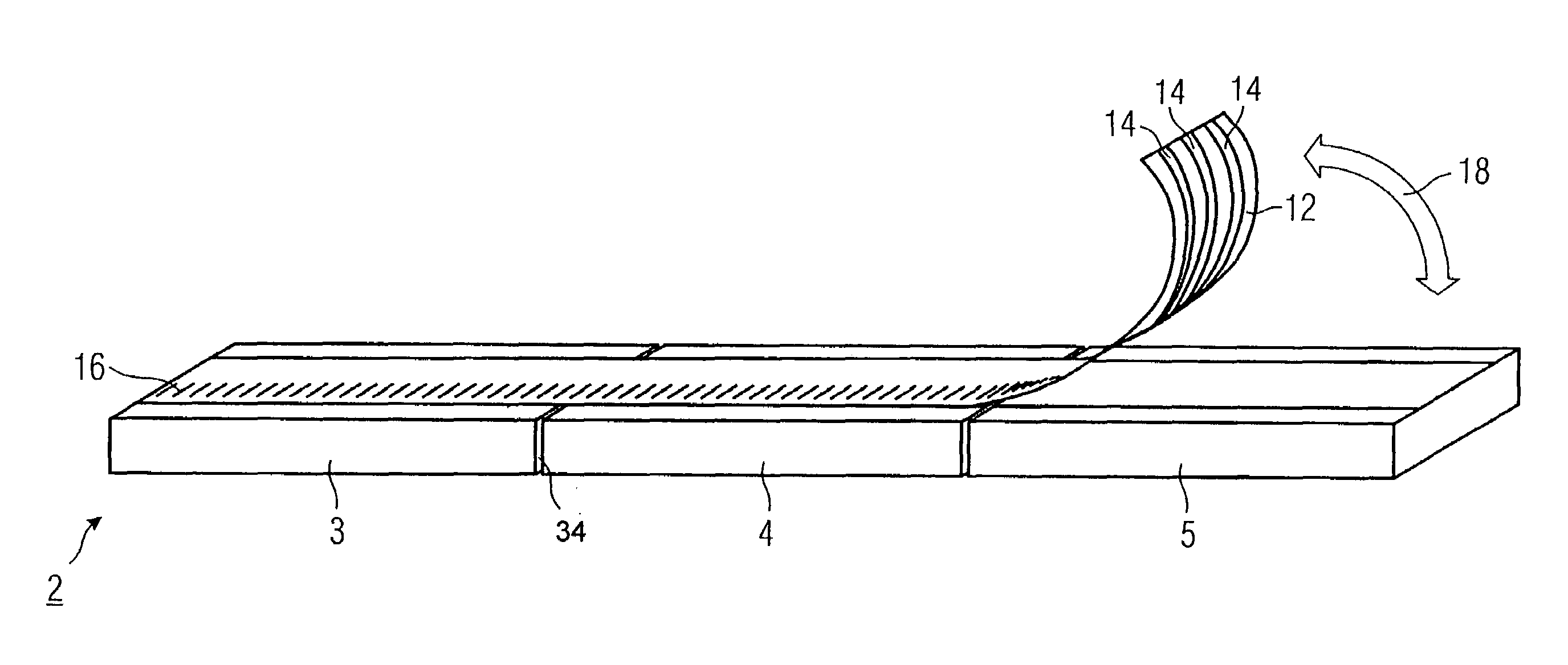
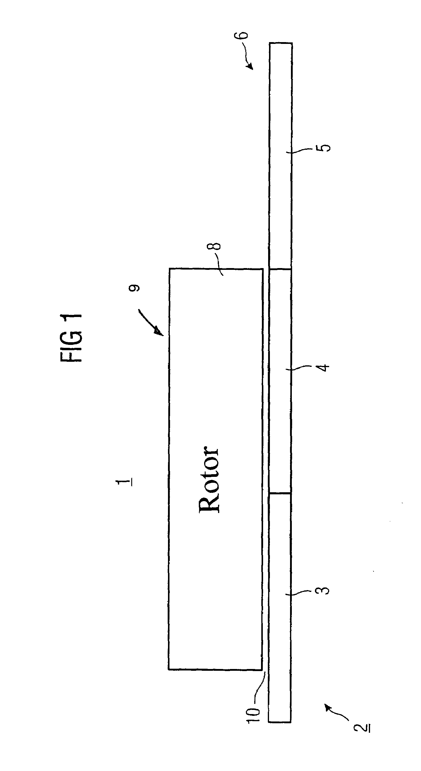
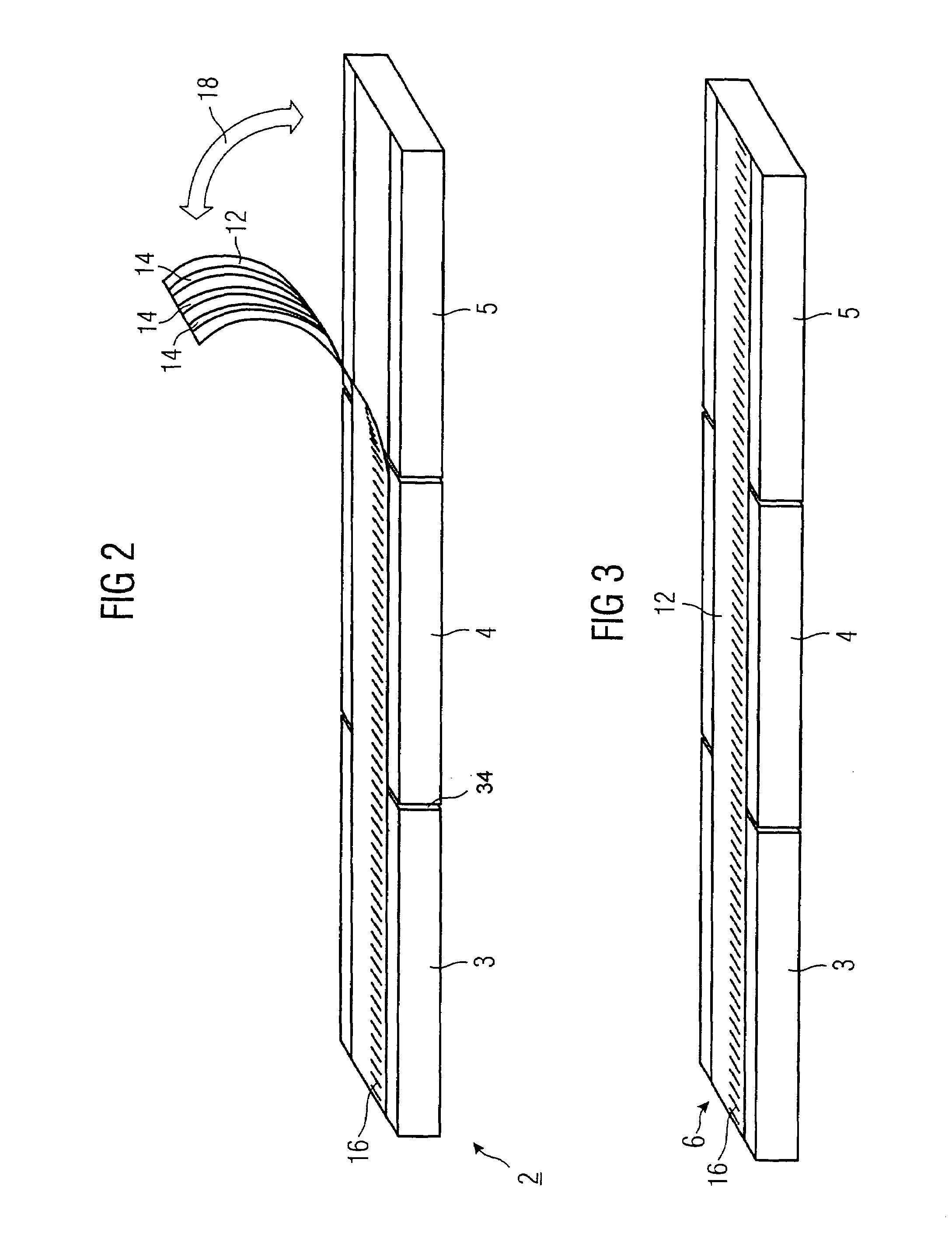
[0022]As the material is sufficiently firm against mechanical stress and can be designed as a single-piece web for stable positioning on the secondary, the provision of a length scale onto the material, for example, by engraving, imprinting, bonding etc. is possible. Such length scales, which are used for operation of a linear motor for position control, have been attached heretofore laterally on the secondary and read by a reading head on the rotor. This lateral attachment has, however, the effect that a possible horizontal tilting of the rotor with respect to the secondary may cause a measuring error in longitudinal direction of the scale. By providing the scale on the cover of the secondary, preferably in the center of the guideway, a tilting of the rotor leads only to a lateral shift of the reading head upon the scale but not to a shift in the longitudinal direction, so that the configuration according to the invention leads to a more accurate measurement of the position.

Problems solved by technology

The hereby created butt-joints are, however, disadvantageous in particular when exposed to rough whether, because dust, operating liquid, aggressive materials etc. can accumulate there.
In the most adverse case, these solid materials may be snatched by the rotor and forced in the area of the butt-joints into the secondary.
Oftentimes, however, the butt-joints cannot be neutralized adequately, thereby causing unevenness, and thus are subjected to the afore-mentioned mechanical stress; However, also other regions can be damaged fairly easily.
As they are glued onto the guideways of the secondary member, replacement is relatively time-consuming and cost-intensive and causes shutdown periods of the machine.
However, as the rotor of the linear motor is concerned here, the afore-stated problems as relating to long stators are not relevant here.
Furthermore, the cover is connected with fasteners, namely screws, for the entire length of the armature so that a simple exchange is not possible.
The magnetic cover can thus shift during operation of the linear motor or even detach from the secondary as the static friction between cover and secondary is not sufficient.

Method used


Image

  • Linear motor, and secondary for a linear motor
  • Linear motor, and secondary for a linear motor
  • Linear motor, and secondary for a linear motor

Examples


Embodiment Construction

[0042]Throughout all the Figures, same or corresponding elements are generally indicated by same reference numerals. These depicted embodiments are to be understood as illustrative of the invention and not as limiting in any way. It should also be understood that the drawings are not necessarily to scale and that the embodiments are sometimes illustrated by graphic symbols, phantom lines, diagrammatic representations and fragmentary views. In certain instances, details which are not necessary for an understanding of the present invention or which render other details difficult to perceive may have been omitted.

[0043]Turning now to the drawing, and in particular to FIG. 1, there is shown a simplified schematic illustration of a linear motor 1 having a primary, generally designated by reference numeral 9 and representing a rotor 8, and a secondary, generally designated by reference numeral 2. The rotor 8 and the secondary 2 are disposed at a distance to one another to define an air ga...


PUM


Abstract

A secondary for a linear motor includes a body comprised of at least one secondary member for defining a guideway for a rotor of the linear motor and a cover including magnetizable material for the guideway. Disposed between the secondary member and the cover is an anti-skid layer to secure the cover against displacement.

Description

CROSS-REFERENCES TO RELATED APPLICATIONS[0001]This application claims the priority of German Patent Application, Serial No. 103 18 207.1, filed Apr. 22, 2003, pursuant to 35 U.S.C. 119(a)–(d), the disclosure of which is incorporated herein by reference.BACKGROUND OF THE INVENTION[0002]The present invention relates to the field of linear motors, and in particular to linear motors having a primary and a covered secondary.[0003]In general, a linear motor includes a, normally fixed, secondary or reactive part, having in case of a synchronous linear motor a plurality of magnetic elements (permanent magnets) arranged side-by-side to define a guideway for a rotor which is movable relative thereto and represents the primary part of the linear motor. The rotor interacts with the magnets of the secondary and converts this interaction into a translatory motion.[0004]Such linear motors are used as drives in various technological fields, for example, in machine tools, machining devices such as a...

Claims


Application Information

Patent Timeline
Patent Type & Authority Patents(United States)
IPC IPC(8): H02K41/02H02K41/03
CPCH02K41/03
Inventor HODZIC, TARIKMATSCHEKO, GERHARD
Owner SIEMENS AG
Why Eureka
Try Eureka