Light guide, illuminating device having the light guide, and image reading device and information processing apparatus having the illuminating device
a technology of light guide and illumination state, which is applied in the direction of photometry using electric radiation detectors, optical radiation measurement, instruments, etc., can solve the problems of high cost, difficult to achieve a sufficiently low cost, and extremely uneven illumination state, so as to reduce the electric power consumption and low cost
- Summary
- Abstract
- Description
- Claims
- Application Information
AI Technical Summary
Benefits of technology
Problems solved by technology
Method used
Image
Examples
embodiment 1
[Embodiment 1]
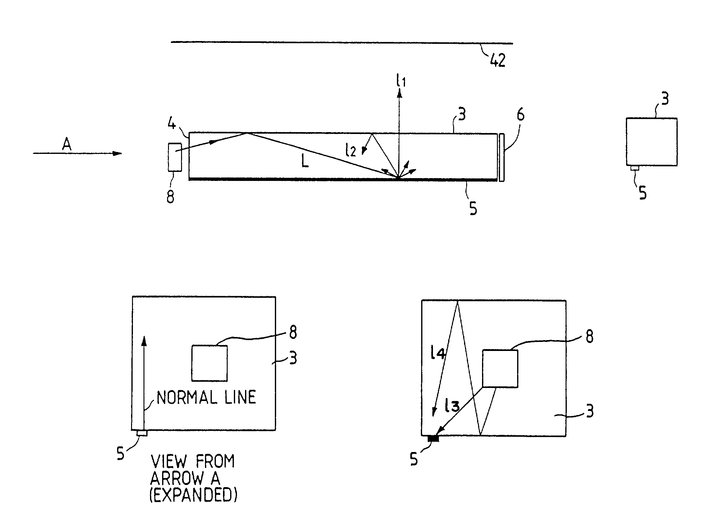
[0103]FIG. 10 is a perspective view showing an embodiment 1 of the linear light source of the present invention, wherein shown are an oblong transparent (translucent) member 3, substrates 45; LED chips 71 mounted on the substrates 45, and a light emitting direction 11. A lateral face 3a of the transparent member 3 constitutes the light emitting face, while other lateral faces 3b, 3c and 3d are formed as mirror faces to constitute light reflecting faces.
[0104]The oblong transparent member 3 is provided at both ends thereof with the LED chips 71 constituting the light sources, and the light therefrom enters the transparent member 3 from the end faces thereof and is emitted from the lateral face 3a in the direction 11 either directly or after reflection on the lateral faces 3b, 3c, 3d. In this embodiment, the lateral face 3d is tapered so that the transparent member 3 has a smaller cross section at the center, whereby the light can be efficiently reflected in the directio...
embodiment 2
[Embodiment 2]
[0106]FIG. 12 shows the elevation view of an embodiment 2 of the linear light source of the present invention, seen from the direction A shown in FIG. 10, and the light amount distribution on an illuminated surface (not shown). Components that are the same as those shown in FIGS. 10 and 11 are represented by the same numbers and will not be explained further.
[0107]In the present embodiment, the lateral face 3d of the oblong transparent member 3 is tapered so as to reduce the cross section thereof at the center as in Embodiment 1, and the transparent member 3 is formed so as to have a trapezoidal cross section having the shorter side at the light emitting face and the longer side at the opposite face. Such a trapezoidal cross section, as shown in FIG. 12, allows the light to be emitted in the transparent member 3, in a more condensed state, into the direction 11, thereby increasing the illumination intensity on the illuminated surface, in comparison with Embodiment 1, w...
embodiment 3
[Embodiment 3]
[0108]FIG. 14 is a plan view of an embodiment 3 of the linear light source of the present invention, seen from a direction B shown in FIG. 10, and FIG. 16 shows the elevation view of the embodiment seen from a direction B shown in FIG. 10 and the light amount distribution. Components that are the same as those shown in FIGS. 10 and 11 are represented by the same numbers and will not be explained further.
[0109]As shown in FIG. 14, the oblong transparent member 3 of this embodiment is provided, in the vicinities of the light sources on the light emitting lateral face 3a, with light attenuating films 306, which attenuate the light emitted from the vicinity of the light sources, thereby providing a light amount distribution, as shown in FIG. 16, on the illuminated surface.
[0110]The attenuating films 306 may be replaced by light shielding films 307 for reducing the light amount in the vicinity of the light source. FIG. 15 is a plan view showing an example in which the light...
PUM
 Abstract
Description
Claims
Application Information
 - R&D
- Intellectual Property
- Life Sciences
- Materials
- Tech Scout
- Unparalleled Data Quality
- Higher Quality Content
- 60% Fewer Hallucinations
Browse by: Latest US Patents, China's latest patents, Technical Efficacy Thesaurus, Application Domain, Technology Topic, Popular Technical Reports.
© 2025 PatSnap. All rights reserved.Legal|Privacy policy|Modern Slavery Act Transparency Statement|Sitemap|About US| Contact US: help@patsnap.com


