Optical submarine communication system and surge suppressing apparatus of the optical submarine communication system

a communication system and optical submarine technology, applied in the field of optical submarine communication system, can solve the problems of inability to obtain satisfactory surge suppression means, inability to suppress surge by surge protective devices, and more frequent surge entering land cables

Inactive Publication Date: 2006-06-06
MITSUBISHI ELECTRIC CORP
View PDF7 Cites 12 Cited by
  • Summary
  • Abstract
  • Description
  • Claims
  • Application Information

AI Technical Summary

Benefits of technology

[0011]With the view of solving the problem set forth above, it is an object of the present invention to provide an optical submarine communication syste

Problems solved by technology

This results in more frequent surge entering the land cable 2.
This raises a problem in that when a surge caused on the long-distance land cable 2 because of a lightning stroke or disconnection, is going to reach the repeater 5, the surge cannot be suppressed by the surge protective device and the cable grounding at the terminal apparatus 1.
Accordingly, this raises a problem in that a satisfactory surge suppressing means cannot be obtained simply by grounding the land cable.
However, since such a surge protective device is provided to prevent a surge from passing a path including the surge protective device and from reaching a main circuit of the repeater 5, it does not have the

Method used


Image

  • Optical submarine communication system and surge suppressing apparatus of the optical submarine communication system
  • Optical submarine communication system and surge suppressing apparatus of the optical submarine communication system
  • Optical submarine communication system and surge suppressing apparatus of the optical submarine communication system

Examples


first preferred embodiment

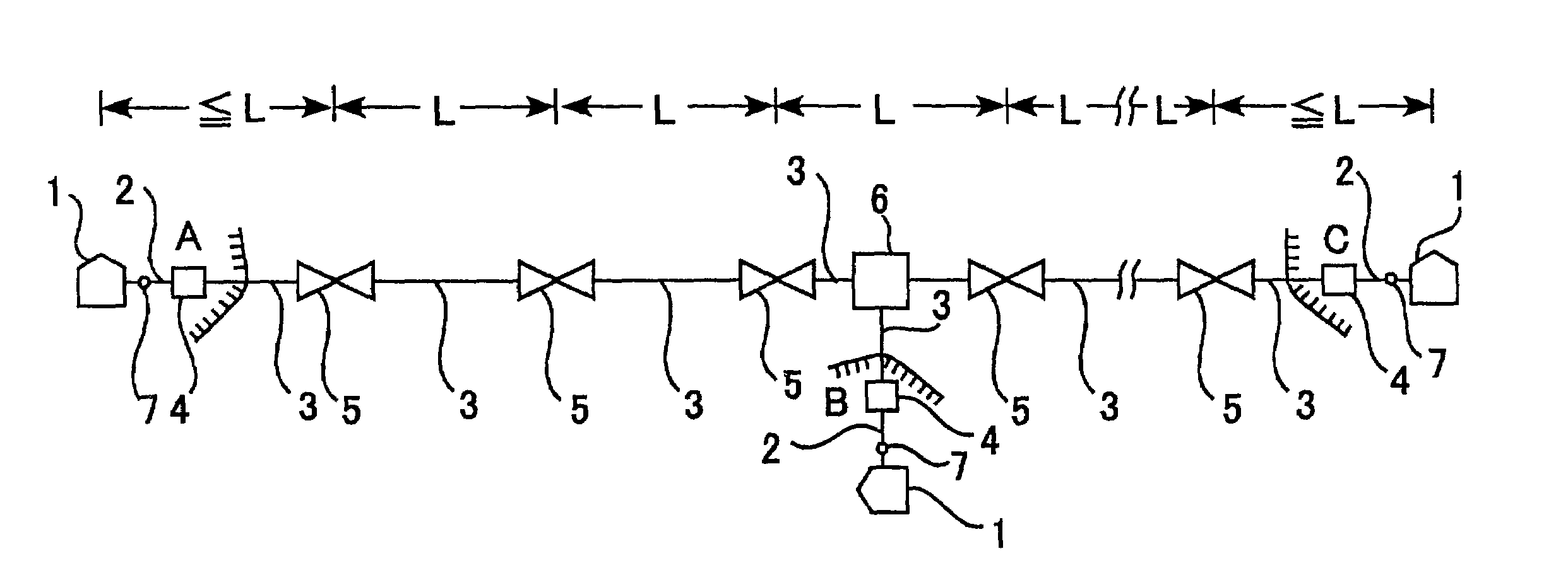
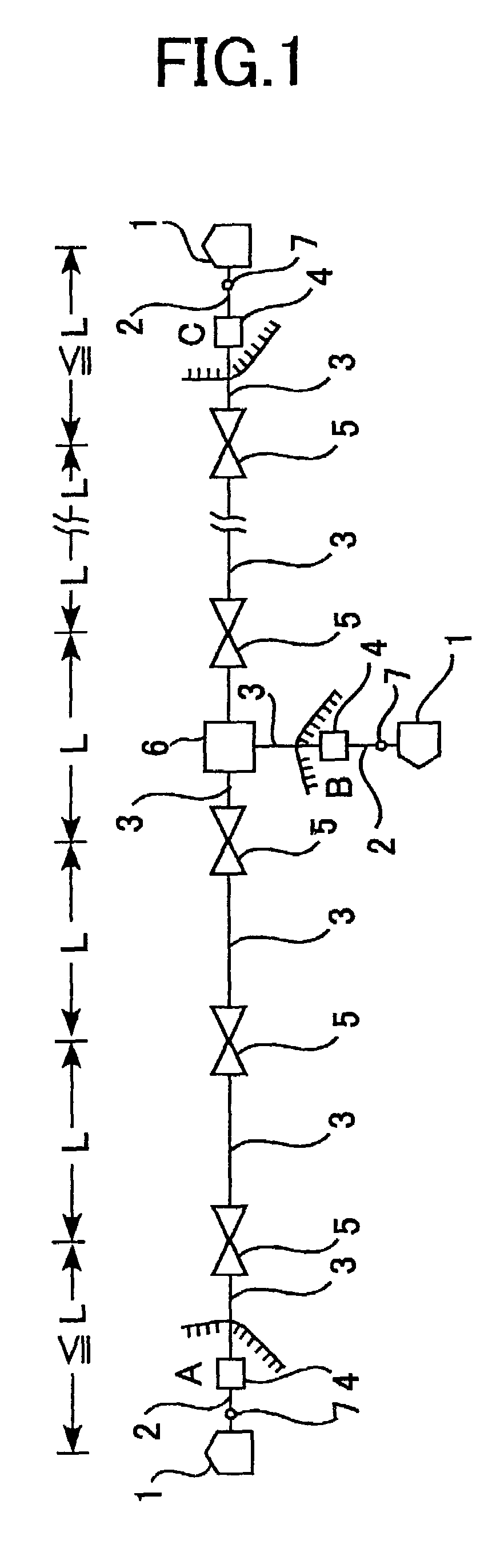
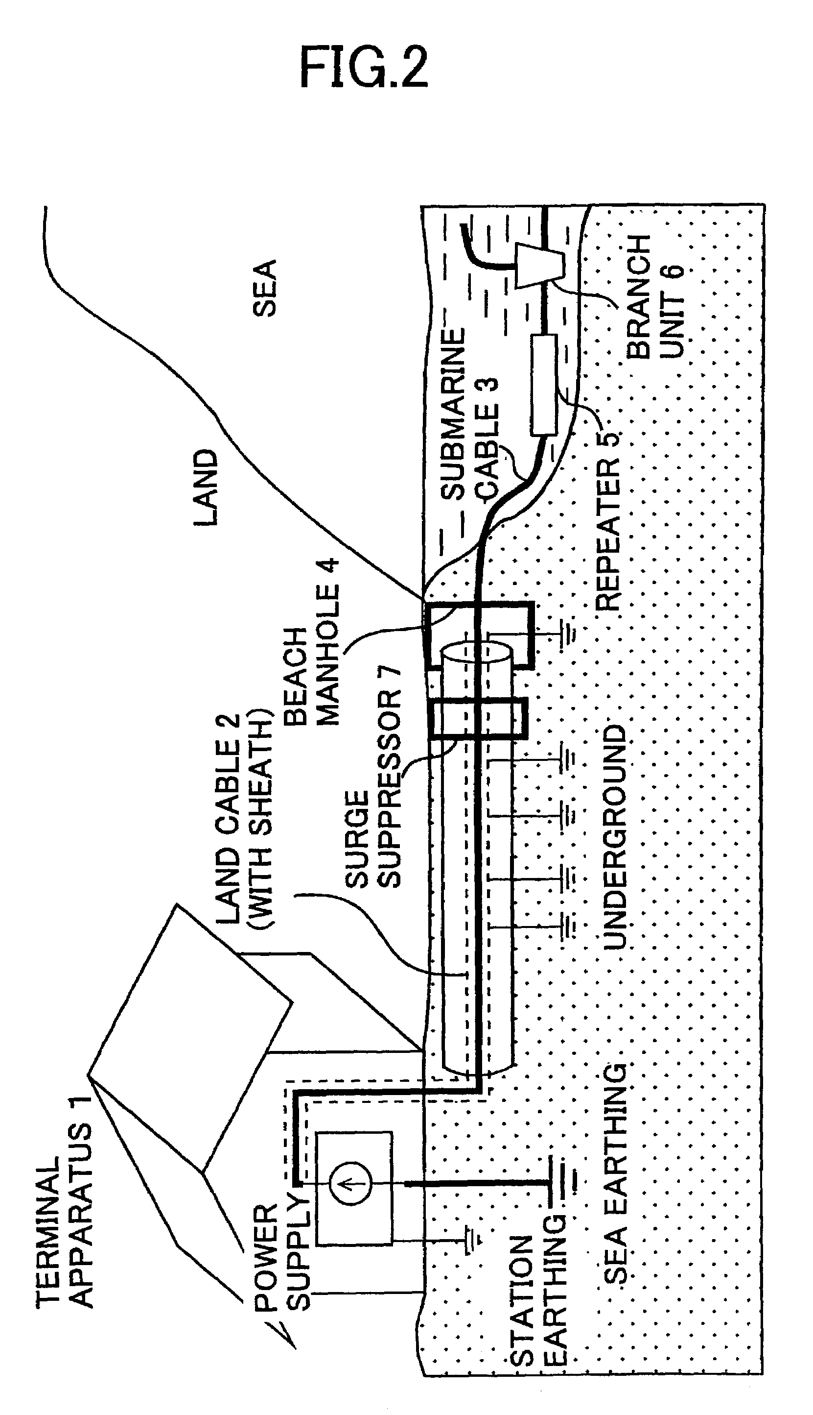
[0034]FIG. 1 is an explanatory view showing a schematic arrangement of an optical submarine communication system according to a first preferred embodiment of the present invention, and FIG. 2 is an explanatory view showing a manner in which a land terminal station, a land cable and an optical submarine cable are connected in the optical submarine communication system. Referring to FIGS. 1 and 2, numeral 1 denotes a terminal (station) apparatus installed near the seashore of each of lands, e.g., lands A, B and C for transmitting an optical signal and electric power, and 2 denotes a land cable connected between the terminal apparatus 1 and a beach manhole 4. The land cable 2 is provided with a surge suppressor 7 which will be described later.

[0035]Numeral 3 denotes an optical submarine cable connected to the land cable 2 through the beach manhole 4 and including an optical fiber and a feeder line for respectively transmitting the optical signal and the electric power from the terminal...

second preferred embodiment

[0042]FIG. 6 is an explanatory view showing a schematic arrangement of an optical submarine communication system according to a second preferred embodiment of the present invention. In FIG. 6, the same symbols as those in FIGS. 1 and 2 denote the same or corresponding components, and a duplicate description of those components is omitted here. This second embodiment differs from the first embodiment in that the surge suppressor is provided in the beach manhole 4 at which the land cable 2 and the optical submarine cable 3 are connected to each other.

[0043]By providing the surge suppressor 7 in the beach manhole 4 for connection to both the land cable 2 and the optical submarine cable 3, even when a surge due to a lightning stroke or an insulation failure, is generated in the land cable 2 between the terminal apparatus 1 and the surge suppressor 7, the generated surge is attenuated by the surge suppressor 7. Therefore, the surge generated in the long-distance land cable 2 because of a...

third preferred embodiment

[0047]A surge suppressor according to a third preferred embodiment of the present invention will be described below. To enable locating of a cut point in the event of an accidental cutting of a cable, the distance from a measuring point to the cut point is determined by sending a count signal with frequency of not more than 50 Hz and measuring the time required for the count signal to go to and return from the cut point after reflection. The surge suppressor of this embodiment is constructed not to attenuate any signal of not more than 50 Hz so that the count signal is allowed to pass the surge suppressor. The surge suppressor includes a filter for attenuating components with frequencies of not less than 50 Hz, while allowing components with frequencies higher than 50 Hz to pass the filter. By employing a cable system, in which at least a feed current has basic frequency of not more than 50 Hz, in an optical submarine communication system provided with the surge suppressor of this e...


PUM


Abstract

An optical submarine communication system has a land cable connected to a terminal apparatus which is installed on land near the seashore for transmitting an optical signal and electric power. The land cable is connected to an optical submarine cable through a beach manhole, and a repeater is connected to the optical submarine cable. The optical submarine communication system has a surge suppressor provided on the land cable, whereby a surge generated from the terminal apparatus side because of a lightning stroke or an insulation failure is suppressed and prevented from reaching and damaging the repeater.

Description

BACKGROUND OF THE INVENTION[0001]1. Field of the Invention[0002]The present invention relates to an optical submarine communication system, and more particularly to an optical submarine communication system comprising a terminal apparatus installed on land for transmitting an optical signal and electric power, a land cable connected to the terminal apparatus, an optical submarine cable connected to the land cable and including an optical fiber and a feeder line for respectively transmitting the optical signal and the electric power from the terminal apparatus, and a repeater connected to the optical submarine cable, driven with the transmitted electric power and amplifying the optical signal, wherein a surge generated from the land cable side because of a lightning stroke or an insulation failure, is suppressed to prevent damaging the repeater.[0003]2. Description of the Related Art[0004]FIG. 19 is an explanatory view showing a schematic arrangement of a conventional optical submari...

Claims


Application Information

Patent Timeline
IPC IPC(8): H04B10/00H04B3/44G02B6/46H04B10/07H04B10/29H04B10/80
CPCH04B10/806
Inventor HORINOUCHI, KATSUHIKOMUTO, HIROTAKAKUMAYASU, SATOSHINAKAOKA, MASAKI
Owner MITSUBISHI ELECTRIC CORP
Why Eureka
Try Eureka