Sliding door assembly for track, step plate, roller, guide and constraint systems

a technology of sliding door and step plate, which is applied in the direction of wing accessories, curtain suspension devices, manufacturing tools, etc., can solve the problems of reducing the service life of the wing

Inactive Publication Date: 2006-06-13
ROSKO PETER J +1
View PDF17 Cites 39 Cited by
  • Summary
  • Abstract
  • Description
  • Claims
  • Application Information

AI Technical Summary

Benefits of technology

[0025]FIG. 13 is a cross sectional view of an optional removable metal guide channel housing (53) within the track (5). The housing includes the removable frame (54), the frame seat (55) with attachment screws (56), a felt or nylon bristle lining (57), a...

Problems solved by technology

Unfortunately, many of these sliding doors are cosmetically designed and are seriously deficient in functional value.
Until now, very little significant improvement has been made by incorporating esthetics, function, safety and security into a single sliding door.
Common complaints include the actual design of the track (its obtrusive “ridges”), the track's affinity for collecting dirt, the deposition of a black metallic residue on the track's surface (caused by the door's metal wheel dragging against its guide rail) and the difficulty in keeping the track clean.
Over time, this stress results in premature wear including breakage of the wheels and door handles.
SAFETY: The traditional sliding door track, predominantly designed with metal rails, is a serious impediment to both foot and wheel traffic.
Even in the presumed safety of one's home, the persistence of this faulty design has caused a multitude of accidents over the years.
Tripping and falling have been common complaints.
This is a more serious problem with t...

Method used


Image

  • Sliding door assembly for track, step plate, roller, guide and constraint systems
  • Sliding door assembly for track, step plate, roller, guide and constraint systems
  • Sliding door assembly for track, step plate, roller, guide and constraint systems

Examples


Embodiment Construction

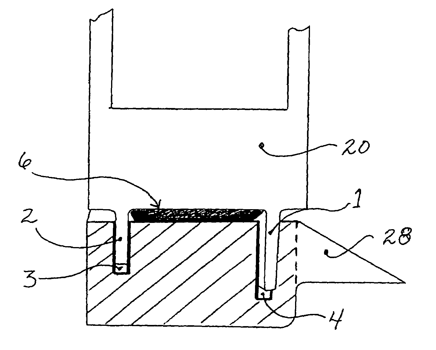
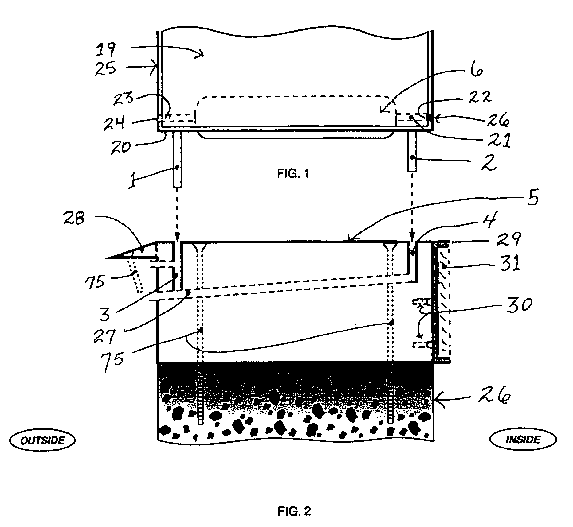
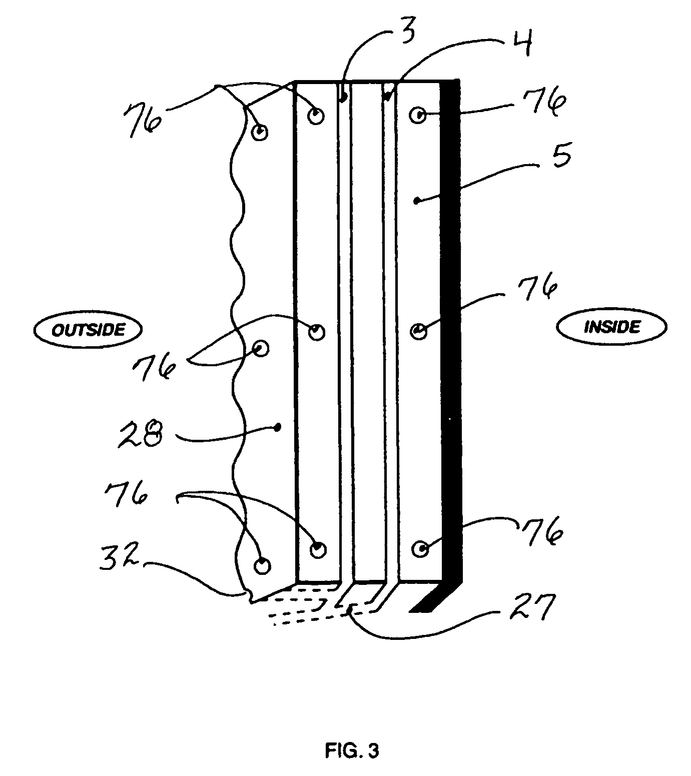
[0040]Utilizing time-proven marine architecture technology, the invention is designed with special attention to strength and stability. One of its innovative features is the elimination of the rails on the traditional sliding track. The single-track rail is replaced with a pair of solid metal rails referred to as the outside and inside guides. This is similar to a “tipsy” single hull boat being replaced with the more stable twin hulls of a catamaran. To further increase its stability against displacement, the outside guide is made longer than the inside guide. The same principle is incorporated in sailboats.. the longer the keel, the greater the stability.

[0041]The core of the invention consists of two occluding sections. The lower, or track, section which consists of the outside and inside guide channels running along the entire length of a smooth and level track. The inside section of the track is cornered at a 90-degree angle to match the level of the floor in the inside room. Th...


PUM


Abstract

The invention corrects three major safety and security problems, associated with millions of traditional sliding doors. It offers a dramatic, yet simplistic, solution to these chronic problems in addition to providing a smooth, maintenance-free operation. The invention eliminates the protruding longitudinal rails of the traditional floor track that create a barrier to foot and wheel traffic. In its place is a smooth, level track that conforms to the “Americans with Disabilities Act of 1990”. Secondly, the invention is secure against unauthorized (forced) entry. Thirdly, the invention is not displaced by hurricane-force winds. For maximum strength and function, solid nylon rollers are positioned at each end between metal guides running the length of the panel base. Adjustable constraints are positioned at each end on top of each panel. The combination of the pair of guides seated into their respective track channels, and the constraints, prevent unauthorized entry and displacement.

Description

BACKGROUND OF THE INVENTION[0001]Traditional sliding glass doors are present in the majority of homes, and many American businesses, across the United States. Unfortunately, many of these sliding doors are cosmetically designed and are seriously deficient in functional value.[0002]Until now, very little significant improvement has been made by incorporating esthetics, function, safety and security into a single sliding door. It is our strong belief that the invention, being submitted with this application, satisfies all of these requirements.Traditional Sliding Doors[0003]ESTHETICS: A traditional sliding door track is primarily designed with a longitudinal metal rail, protruding vertically from its base, to guide each door panel. Common complaints include the actual design of the track (its obtrusive “ridges”), the track's affinity for collecting dirt, the deposition of a black metallic residue on the track's surface (caused by the door's metal wheel dragging against its guide rail)...

Claims


Application Information

Patent Timeline
IPC IPC(8): B61D19/00
CPCE05D15/0665E05D15/0686E06B3/46Y10T16/379E05Y2900/132
Inventor ROSKO, PETER J.SCOTT, LARRY
Owner ROSKO PETER J
Why Eureka
Try Eureka