Hydromechanical closing device, in particular for lateral extrusion

a technology of hydraulic cylinder and lateral extrusion, which is applied in the direction of forging press drives, forging/pressing/hammering apparatuses, manufacturing tools, etc., can solve the problem of external high-pressure hose connection between the two hydraulic cylinders, and achieve the effect of simple and compact construction

Inactive Publication Date: 2006-06-13
HATEBUR UMFORMMASCHEN
View PDF5 Cites 6 Cited by
  • Summary
  • Abstract
  • Description
  • Claims
  • Application Information

AI Technical Summary

Benefits of technology

[0004]The object of the invention is to provide a closing device of the generic type, in particular for the lateral extrusion of work pieces, which has a simple and compact construction and is designed without an external pressure-medium connection between the first hydraulic cylinder and the second hydraulic cylinder.
[0019]A compact and reliably working closing device which can also be used for very high pressures is provided by the invention.

Problems solved by technology

A disadvantage in this case is the external high-pressure hose connection between the two hydraulic cylinders, since use of this moving high-pressure hose is currently only admissible for pressures up to 1000 bar.

Method used


Image

  • Hydromechanical closing device, in particular for lateral extrusion
  • Hydromechanical closing device, in particular for lateral extrusion
  • Hydromechanical closing device, in particular for lateral extrusion

Examples


Embodiment Construction

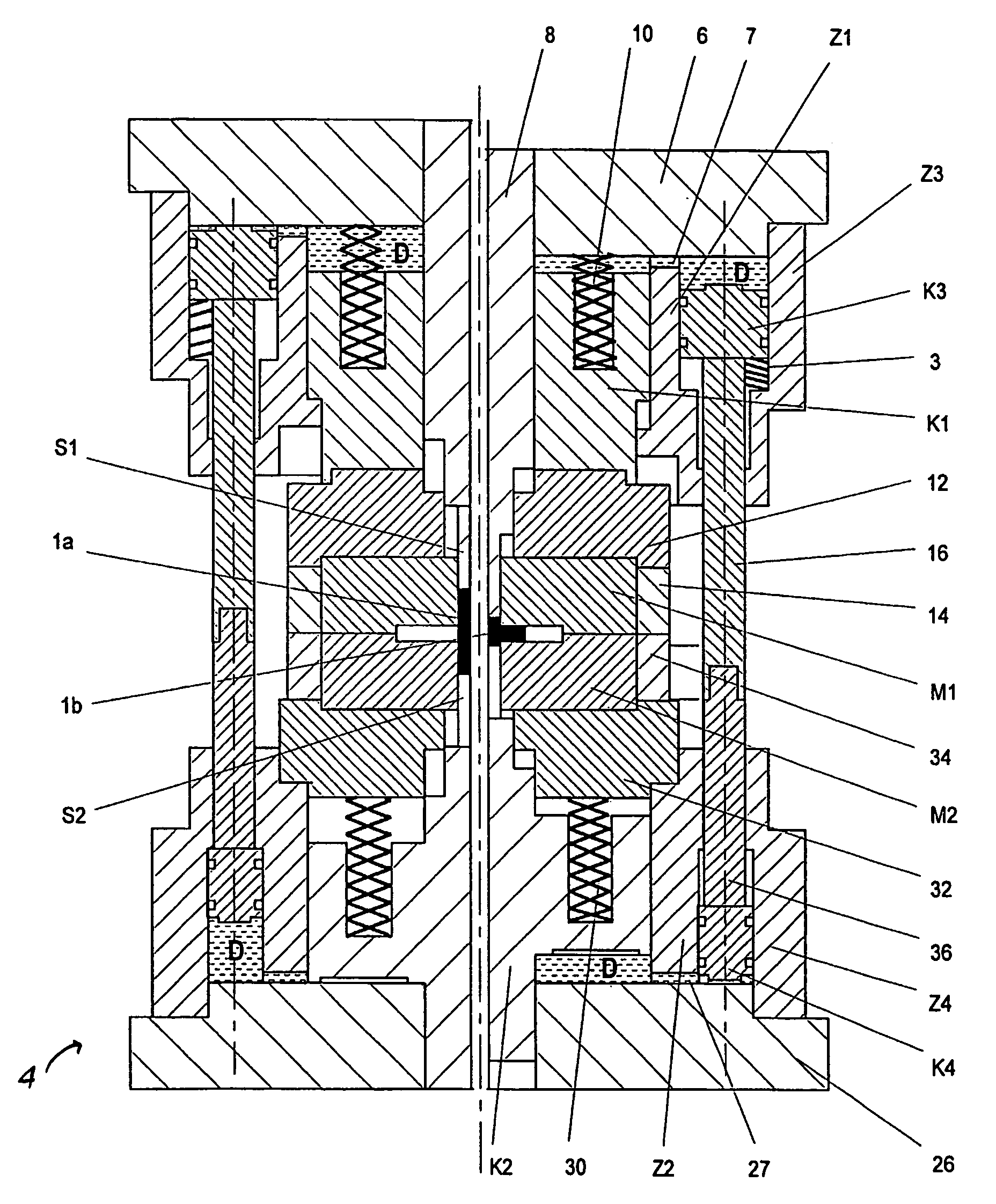
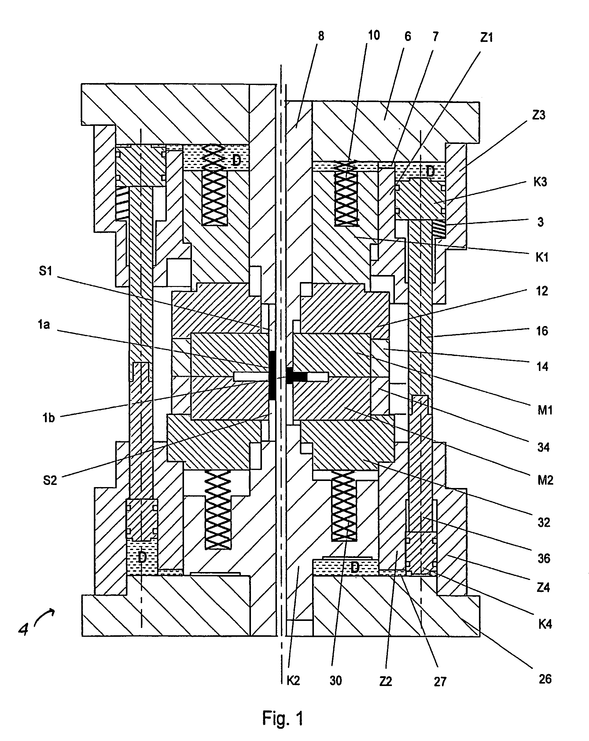
[0028]The left-hand side of the representations in FIGS. 1 and 2 in each case shows the closed closing device with inserted blank 1a, and the right-hand side shows the closing device after completion of the lateral extrusion.

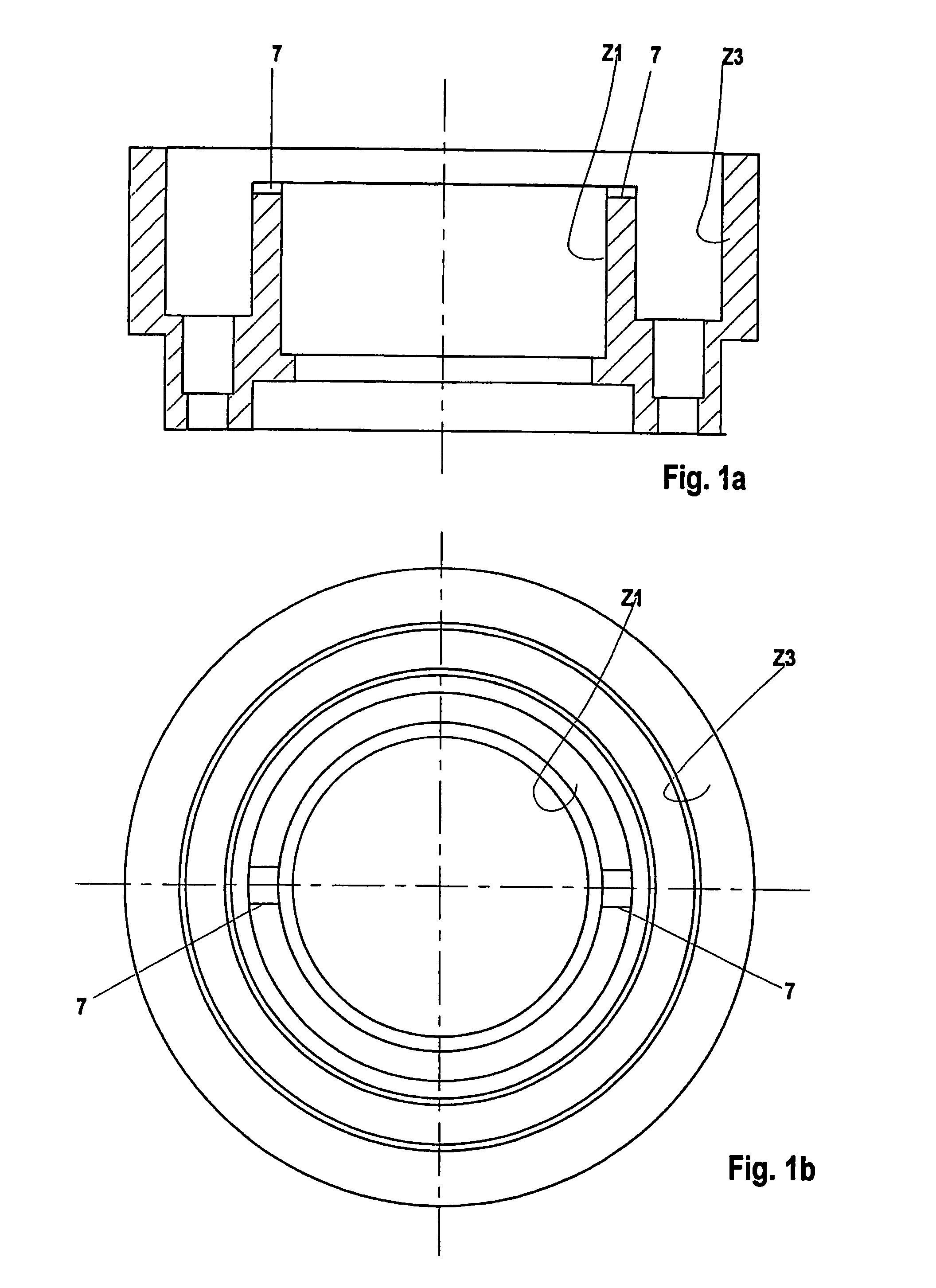
[0029]The closing device shown in FIG. 1 has a vertically movable top tool half and a bottom tool half fixed to the frame. The top tool half comprises an intermediate plate 6 which is fastened to the ram (not shown). A pressure piece 8, on which the first punch S1 sits, is arranged essentially centrally on the intermediate plate 6. Furthermore, the first hydraulic cylinder Z1 and the third hydraulic cylinder Z3 are fastened to the intermediate plate 6. The first hydraulic cylinder Z1 and the third hydraulic cylinder Z3 are designed as a construction unit, there being a connection in the form of a channel 7 between the hydraulic cylinders Z1 and Z3.

[0030]Guided in the first hydraulic cylinder Z1 is the first hydraulic piston K1, through which the pressure piece 8...


PUM

PropertyMeasurementUnit
pressuresaaaaaaaaaa
speedsaaaaaaaaaa
pressureaaaaaaaaaa

Abstract

The invention relates to a hydromechanical clamping device having two movable die halves and two punches, a first hydraulic piston, and a second hydraulic piston. The second die half is fixed to the frame and the second punch is arranged on the second hydraulic piston. The first hydraulic cylinder is connected to a third hydraulic cylinder. The latter acts on a fourth hydraulic piston. The first hydraulic cylinder is connected to the third hydraulic cylinder, so that the pressure medium displaced from the first hydraulic cylinder during a feed movement flows into the third hydraulic cylinder and the third hydraulic piston moves the fourth hydraulic piston in the feed direction, so that pressure medium is displaced into the second hydraulic cylinder, and the requisite forming pressure can be applied to the second hydraulic piston and the punches move toward one another.

Description

FIELD OF THE INVENTION[0001]The invention relates to a hydromechanical closing device, in particular for the lateral extrusion of work pieces.BACKGROUND OF THE INVENTION[0002]During lateral extrusion, pressure is applied to a work piece between two punches in such a way that some of the material flows—transversely to the press direction—into cavities formed by die halves.[0003]A hydraulic closing device for lateral extrusion of work pieces is disclosed according to DE 199 22 659 A1, this closing device having two die halves which can be moved relative to one another and can be closed together and two punches which can be moved at the same speeds relative to the closed die halves, a first hydraulic piston, on which the first die half is arranged, being mounted in a displaceable manner in an axially movable first hydraulic cylinder, and a second hydraulic piston being mounted in a displaceable manner in a spatially fixed second hydraulic cylinder. The first punch is fastened via a pun...

Claims


Application Information

Patent Timeline
Patent Type & Authority Patents(United States)
IPC IPC(8): B21J9/12B21J9/10B21J5/06B21C23/21B21J5/02
CPCB21J5/02B21C23/21
Inventor SIEGERT, KLAUSSCHWAGER, ARIBERTKAMMERER, MANFRED
Owner HATEBUR UMFORMMASCHEN
Why Eureka
Try Eureka