
Buoyancy can for offshore oil and gas riser

a technology for oil risers and booms, applied in the field of booms, can solve the problems of high cost, high labor intensity, and high labor intensity, and achieve the effect of reducing the stress and strain on the booms

Active Publication Date: 2006-06-13
TECH FRANCE SA
View PDF15 Cites 19 Cited by
  • Summary
  • Abstract
  • Description
  • Claims
  • Application Information

AI Technical Summary

Benefits of technology

Enables efficient coupling and decoupling of the buoyancy can to the riser without removing the upper terminal end, reducing stress and strain on the riser and simplifying operations by distributing lateral loads and allowing precise buoyancy control.

Problems solved by technology

This results in a fairly complex, time-consuming, expensive, and potentially risky operation, particularly if effected in moderate or heavy seas.

Method used


Image

  • Buoyancy can for offshore oil and gas riser
  • Buoyancy can for offshore oil and gas riser
  • Buoyancy can for offshore oil and gas riser

Examples


Embodiment Construction

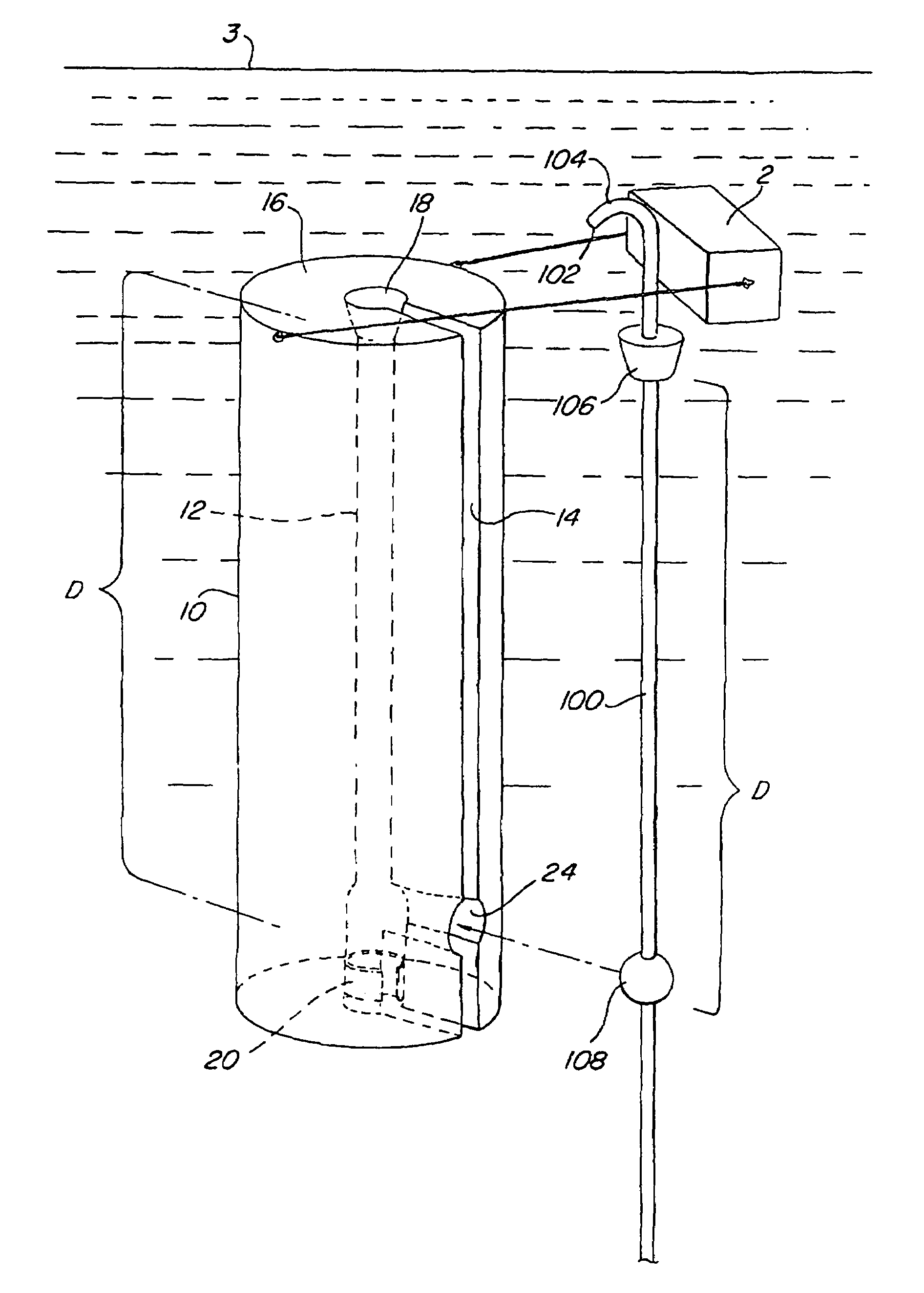
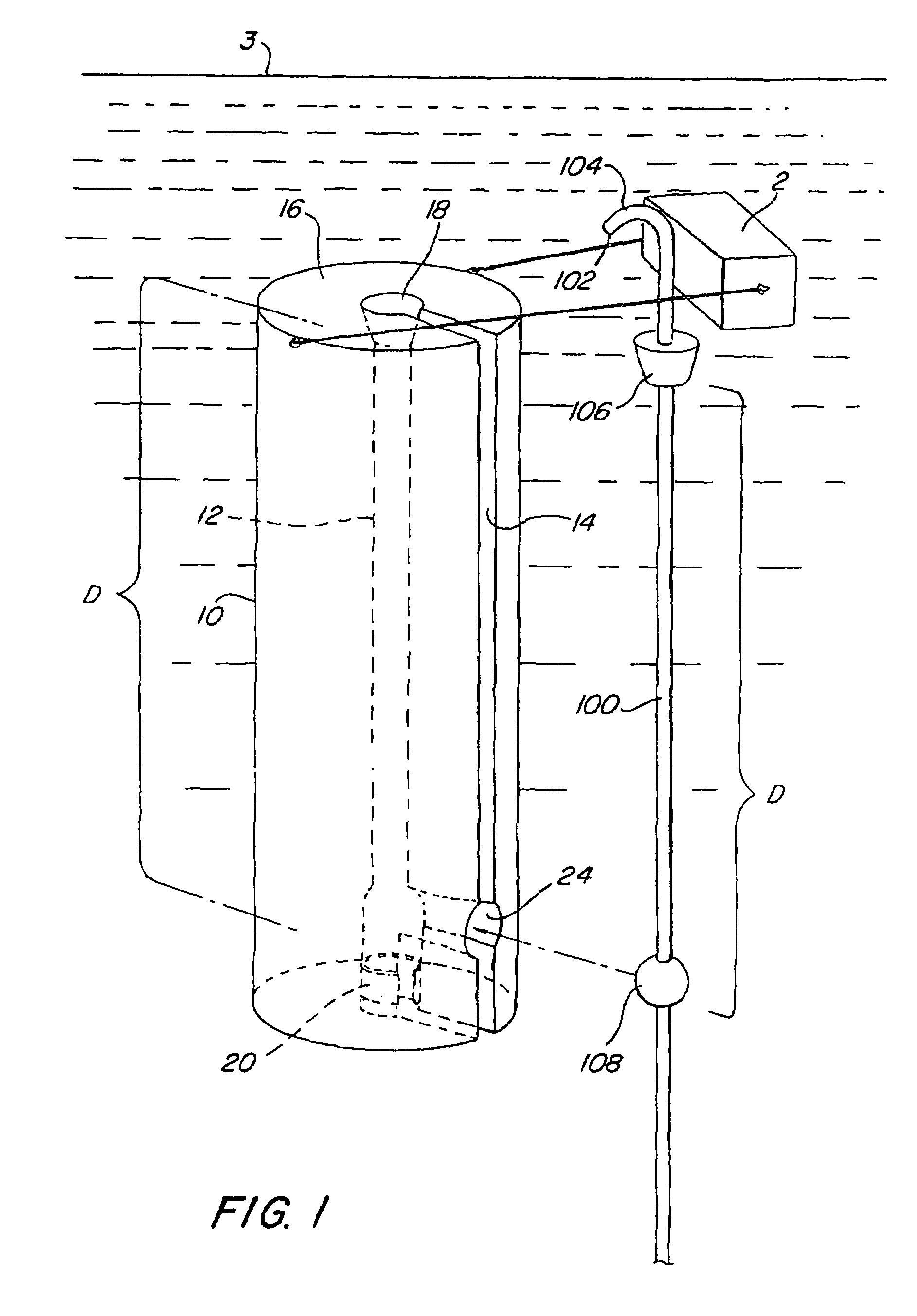
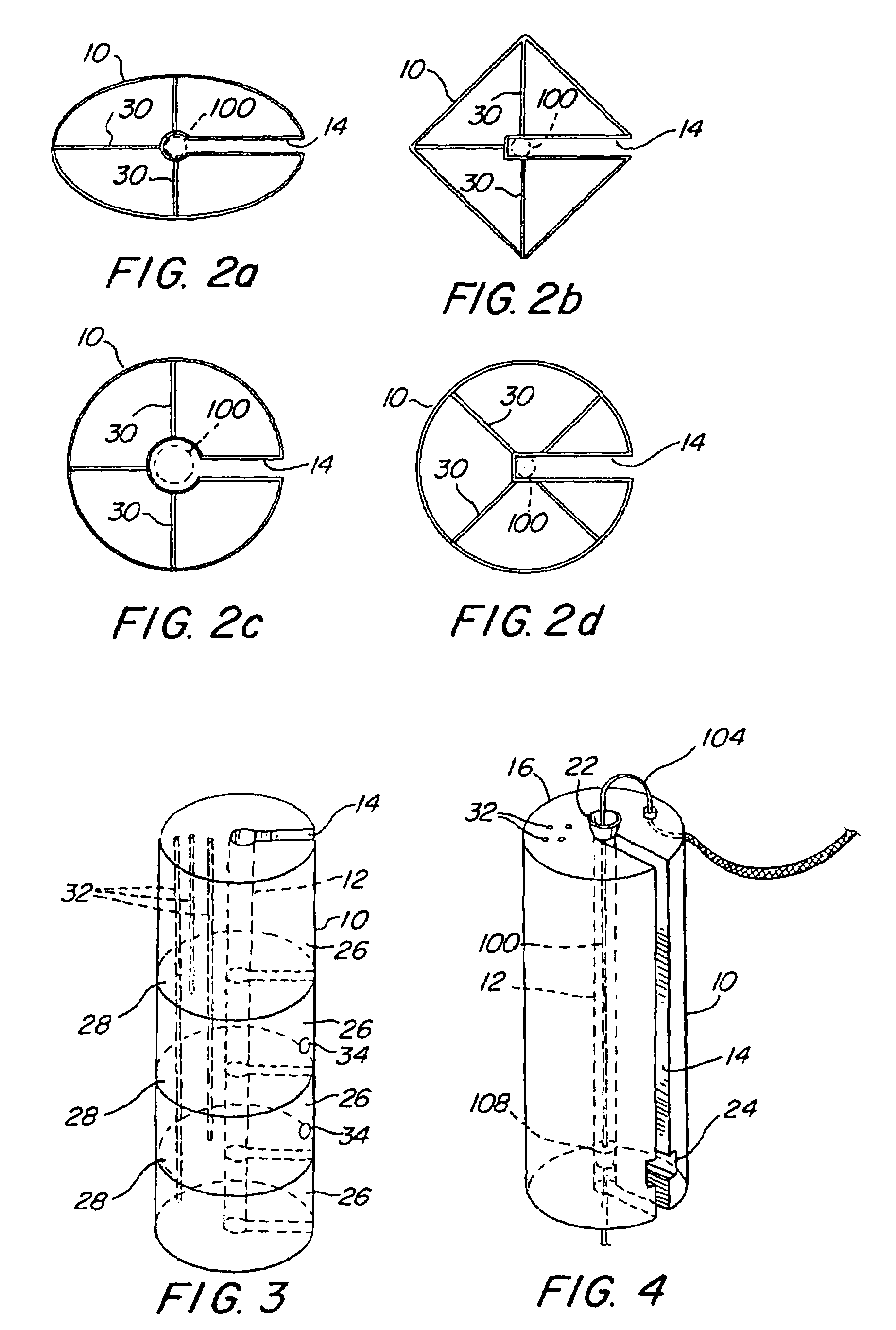
[0030]A perspective view of an exemplary embodiment of a buoyancy can 10 in accordance with the present invention being deployed in a body of water and coupled to the upper end portion of an associated offshore oil and gas riser 100 is illustrated in FIG. 1. The buoyancy can comprises a single vertical axial bore 12 through which the riser extends coaxially in a conventional manner, and a radio-axial slot 14 that extends through a side of the can and into the axial bore. The slot 14 has a width that is greater than the diameter of the riser 100 to enable the riser to pass through the slot laterally and into the axial bore 12.

[0031]For simplicity of description, the particular embodiment of buoyancy can 10 and riser 100 described and illustrated herein is shown to include only a single axial bore 12 and corresponding single riser. However, a typical hybrid riser “tower” may include a buoyancy can 10, such as that illustrated in FIG. 10, which supports several such risers simultaneous...


PUM


Abstract

A buoyancy can for supporting an offshore oil and gas riser includes an axial bore through which the riser extends coaxially, and a radio-axial slot extending through a side of the can and into the axial bore. A pair of spaced-apart support features are disposed coaxially on the riser, and the can includes a pair of corresponding sockets in the axial bore thereof. The sockets are adapted to receive and vertically support respective ones of the support features in a complementary, axial engagement. The can is placed in the water and moved laterally relative to a fully assembled, vertically supported riser such that the riser passes through the radio-axial slot of the can and into the axial bore thereof without the need for disassembly of the upper portion of the riser. The relative vertical positions of the can and riser are then adjusted such that the support features engage and seat within respective ones of their complementary sockets.

Description

CROSS-REFERENCE TO RELATED APPLICATIONS[0001](Not Applicable)STATEMENT REGARDING FEDERALLY SPONSORED RESEARCH OR DEVELOPMENT[0002](Not Applicable)REFERENCE TO APPENDIX[0003](Not Applicable)BACKGROUND OF THE INVENTION[0004]1. Field of the Invention[0005]This invention relates, in general, to methods and apparatus for offshore oil and gas production, and in particular, to a buoyancy can for tensioning, or supporting, the upper end of an offshore oil and gas riser that can be coupled to and decoupled from the riser without disassembling the upper terminal end portion thereof.[0006]2. Related Art[0007]Top-tensioned riser (“TTR”) systems for offshore oil and gas production (see, e.g., U.S. Pat. No. 4,702,321 to E. E. Horton) use passive “buoyancy cans” to support the risers independently of an associated floating production platform. In such a system, the riser extends vertically upward from the sea floor through the keel of the platform, and thence, to the well deck thereof, where it co...

Claims


Application Information

Patent Timeline
Patent Type & Authority Patents(United States)
IPC IPC(8): E21B29/12E21B17/01
CPCE21B17/012
Inventor DAILEY, JAMES ELVINKARAYAKA, METIN
Owner TECH FRANCE SA
Learn More