Hybrid gas inflator

Active Publication Date: 2006-06-13
NAT CHUNG SHAN INST SCI & TECH
View PDF17 Cites 18 Cited by
  • Summary
  • Abstract
  • Description
  • Claims
  • Application Information

AI Technical Summary

Benefits of technology

[0005]Accordingly, the primary object of the present invention is to provide a hybrid gas inflator that ejects a hot gas (a second gas), generated in a combustion chamber, into a high-pressure gas container to heat up

Problems solved by technology

It is a disadvantage that this mechanism needs a larger quantity of gas and therefore the weight and size of the gas container cannot be too small.
But the solid impurities in the gas, a byproduct of combustion, are hazardous to

Method used


Image

  • Hybrid gas inflator
  • Hybrid gas inflator
  • Hybrid gas inflator

Examples


Embodiment Construction

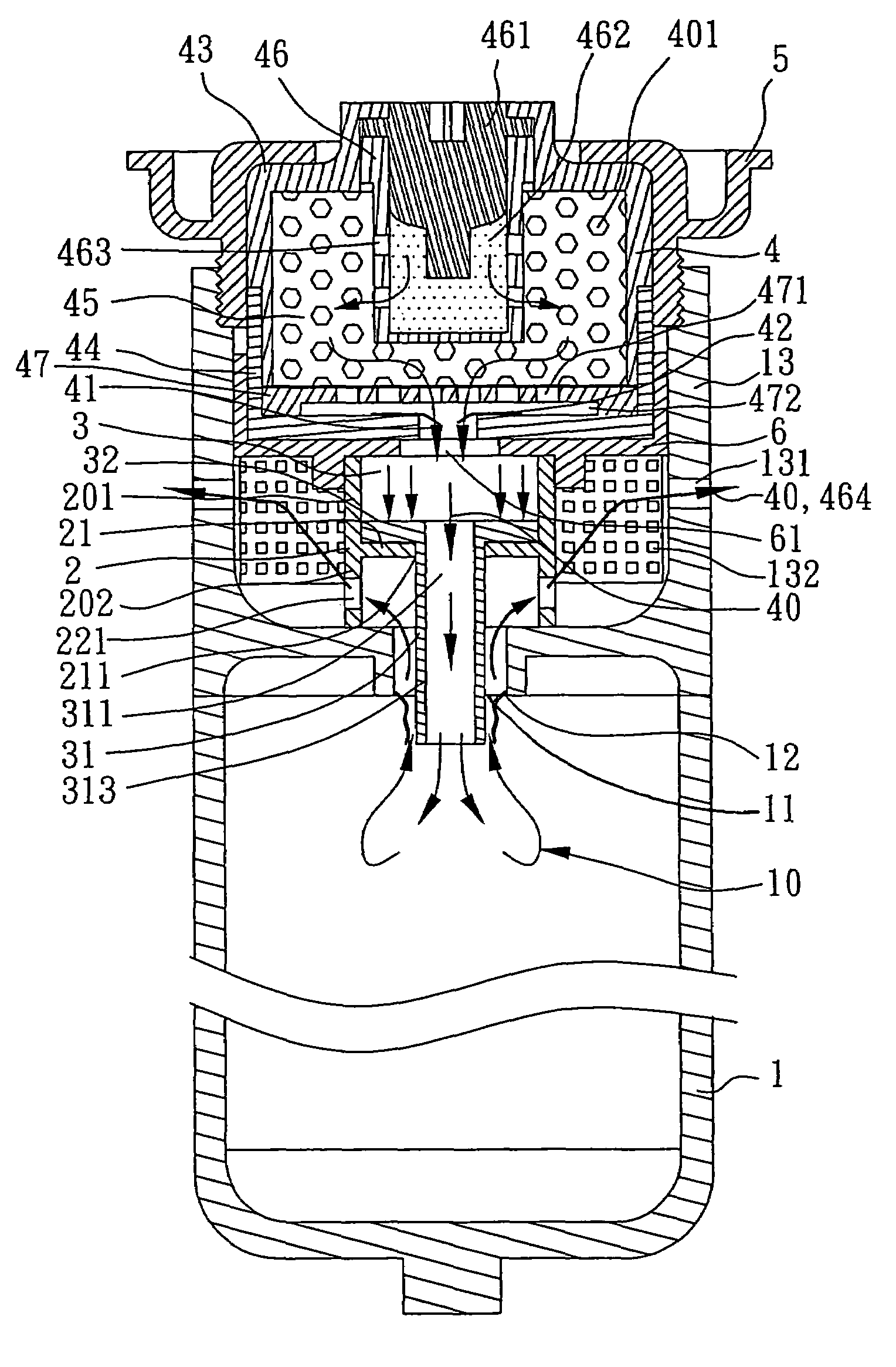
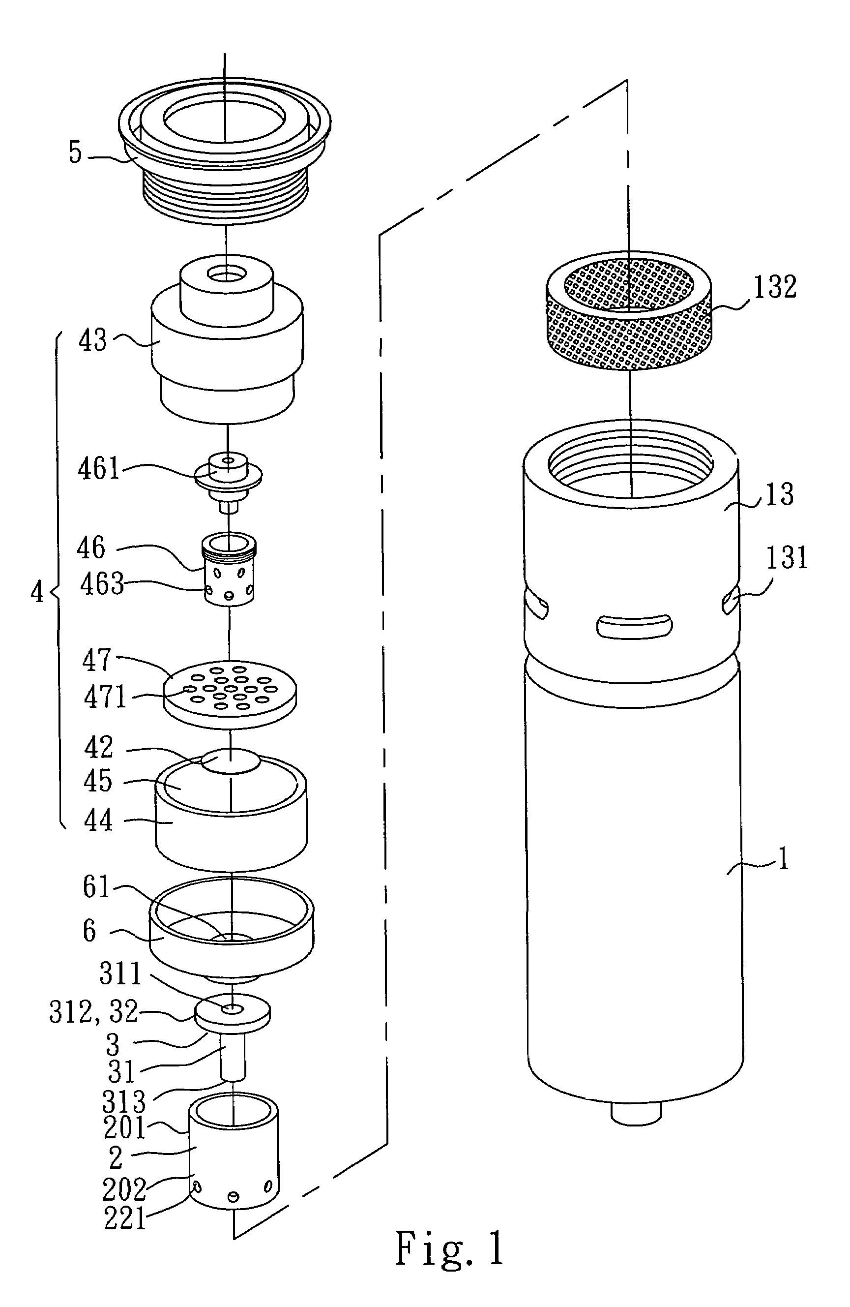
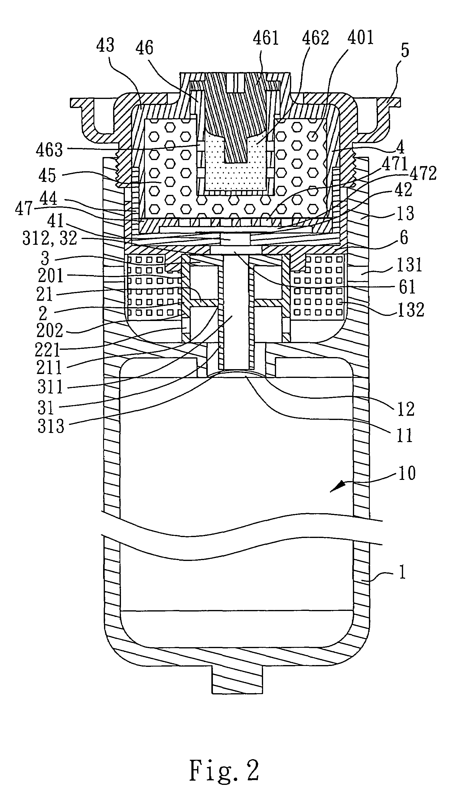
[0019]Referring to FIG. 1, a hybrid gas inflator according to the present invention comprises a high-pressure gas container 1, a connecting ring 2, a piston 3, and a combustion chamber 4. FIG. 2 shows a cross-sectional view of the present invention when a process of inflation has not activated. The high-pressure gas container 1 can be a steel gas cylinder or a gas cylinder made of other materials. In this embodiment it is a steel gas cylinder in which a first gas 10 is stored. An opening 11 is formed on the top of the high-pressure gas container 1 and sealed by a pressure-resisting disc 12. In this embodiment the pressure-resisting disc 12 is a stainless steel disc; it can also be made of an aluminum, a flexible metallic or a flexible non-metallic disc. Further, an extension ring portion 13 is formed on the top of high-pressure gas container 1 surrounding the opening 11. A plurality of exhaust outlets 131 in radial arrangement is formed on the wall of the extension ring portion 13.

[...


PUM


Abstract

A hybrid gas inflator utilizes a combustion chamber to generate a gas of hot jet. The gas pushes a piston downward and flows through a hole of the piston along its axis so as to break a pressure-resisting disc. The gas is then injected into a high-pressure gas container to heat up another gas therein. The hybrid gas gets expanded and is ejected through a plurality of exhaust outlets. This hybrid gas inflator can produce larger gas volume and therefore can reduce the size and weight of an inflator. Further, the impurities in the hybrid gas are congealed fast after two stages of pressure drop and can be removed easily by a filter.

Description

FIELD OF THE INVENTION[0001]The present invention relates to a hybrid gas inflator, and more particularly to a hybrid gas inflator used in the airbags in vehicles.BACKGROUND OF THE INVENTION[0002]For providing passengers with safety protection in accidents, an air bag system has become a standard device of modern day vehicles.[0003]The gas inflation devices of the prior art for car air bags are categorized into full pressurized-gas type, gas-generant type, and hybrid type. The full pressurized-gas type directly uses a high-pressure gas stored in a high-pressure container to inflate an air bag. It is a disadvantage that this mechanism needs a larger quantity of gas and therefore the weight and size of the gas container cannot be too small. On the other hand, the gas-generant type uses propellant or pyrotechnics to generate a high-pressure gas to inflate an air bag; therefore, the size of the inflation device can be made small. But the solid impurities in the gas, a byproduct of combu...

Claims


Application Information

Patent Timeline
IPC IPC(8): B60R21/26B60R21/272F42B3/04
CPCF42B3/045B60R21/272
Inventor WANG, JING-HUEITSAI, TAI HOTSAI, LONG-MING
Owner NAT CHUNG SHAN INST SCI & TECH
Why Eureka
Try Eureka