Vehicular infrared light radiating lamp

a technology of infrared light and lamp, which is applied in the direction of instruments, lighting and heating apparatus, sensing by electromagnetic radiation, etc. it can solve the problems of glare effect, risk of creating light, and inability to adjust so easily, so as to eliminate reduce the risk of glare. , the effect of high energy density

Inactive Publication Date: 2006-06-13
KOITO MFG CO LTD
View PDF4 Cites 10 Cited by
  • Summary
  • Abstract
  • Description
  • Claims
  • Application Information

AI Technical Summary

Benefits of technology

[0016]To eliminate the risk of causing glare with the visible light emitted from the rim portion of the convex lens, however, in the construction where the infrared light transmitting film is formed on the rear surface of the convex lens, light source light (visible light) with a high energy density directed from the rear toward the infrared light transmitting film-free region is blocked by the light shielding member and not directed toward the infrared light transmitting film-free region, and only light (visible light) with a low energy density dampened by repeated reflecting, including reflecting by the infrared light transmitting film and further reflecting by the light shielding member, reaches the infrared light transmitting film-free region. Therefore, white light source light (visible light) with a low energy density is emitted from the rim portion of the convex lens, which is effective for diluting the red light emitted from the convex lens while not creating glare because of its low light intensity. Also in the case where the infrared light transmitting film is formed on a transparent plate disposed to the rear of the convex lens and the light shielding member is provided on the rear of the transparent plate disposed adjacent to the convex lens, results identical to those described above can be obtained.
[0017]In the case where the light shielding member is provided between the convex lens and the transparent plate in a construction where the infrared light transmitting film is formed on a transparent plate disposed to the rear of the convex lens, light source light (visible light) with a high energy density directed from the rear toward the rim portion of the convex lens is blocked by the light shielding member and prevented from reaching the rim portion of the convex lens, and only light (visible light) with a low energy density due to repeated reflection by the rear surface of the convex lens and the front surface of the transparent plate reaches the rim portion of the convex lens. Therefore, white light source light (visible light) with a low energy density is emitted from the rim portion of the convex lens, which is effective for diluting the red light emitted from the convex lens while avoiding the creation of glare because of its low intensity.
[0019]Since in such a case the infrared light transmitting film is formed directly on the convex lens, because no transparent plate for forming the infrared light transmitting film is necessary, the lamp structure is further simplified. In addition, compared to the case in which a separate infrared light transmitting filter is provided, because the interior of the light source unit is less prone to heat up excessively, heat-induced deterioration of the infrared light transmitting film is suppressed.
[0023]In general, die-cast aluminum tends to be used to manufacture the lens holder due to its formability, heat durability, and the like. The lens engaging portion and the light shielding member are integrally formed, extending in a stepped configuration on the front edge portion of the lens holder. In such a construction, therefore, compared to cases where the light shielding member is constructed as a separate member, the structure is simpler, with accompanying ease of manufacturing and no increase in weight.
[0025]When visible light (light source light) reflected by the end face on the extending end portion of the light shielding member is obliquely incident on the infrared light transmitting film, arc-shaped stripes may appear lit red by the light emitted from the convex lens. However, since the tapered extending end portion of the light shielding member does not have an end face with which to reflect visible light (light source light) towards the convex lens, the light source light is not obliquely incident on the infrared light transmitting film, and hence there is no risk of the convex lens appearing lit red.
[0027]When visible light (light source light) reflected by the end face of the extending end portion of the light shielding member is obliquely incident on the infrared light transmitting film, arc-shaped stripes may appear lit red by the light emitted from the convex lens. However, visible light (light source light) is almost completely absorbed by the blackened end face of the extending end portion of the light shielding member and thus is not reflected toward the convex lens. Therefore, the light source light is not obliquely incident on the infrared light transmitting film, and hence there is no risk of the convex lens appearing lit red.

Problems solved by technology

This causes a safety problem in that the infrared light radiating lamp, which is mounted at the front portion of the vehicle, can be mistaken for a tail lamp or a stop lamp.
However, light with a relatively high energy density including direct light from the bulb 2 and reflected light from the reflector 1 and the lens holder 3 is directly incident on the infrared light transmitting film-free region 6 and emitted from the convex lens rim portion 4, thus creating the risk of creating light which causes a glare effect.
However, such an adjustment is not so simple because the reduced light emission reduces the effect of diluting the red light emission.

Method used


Image

  • Vehicular infrared light radiating lamp
  • Vehicular infrared light radiating lamp
  • Vehicular infrared light radiating lamp

Examples


first embodiment

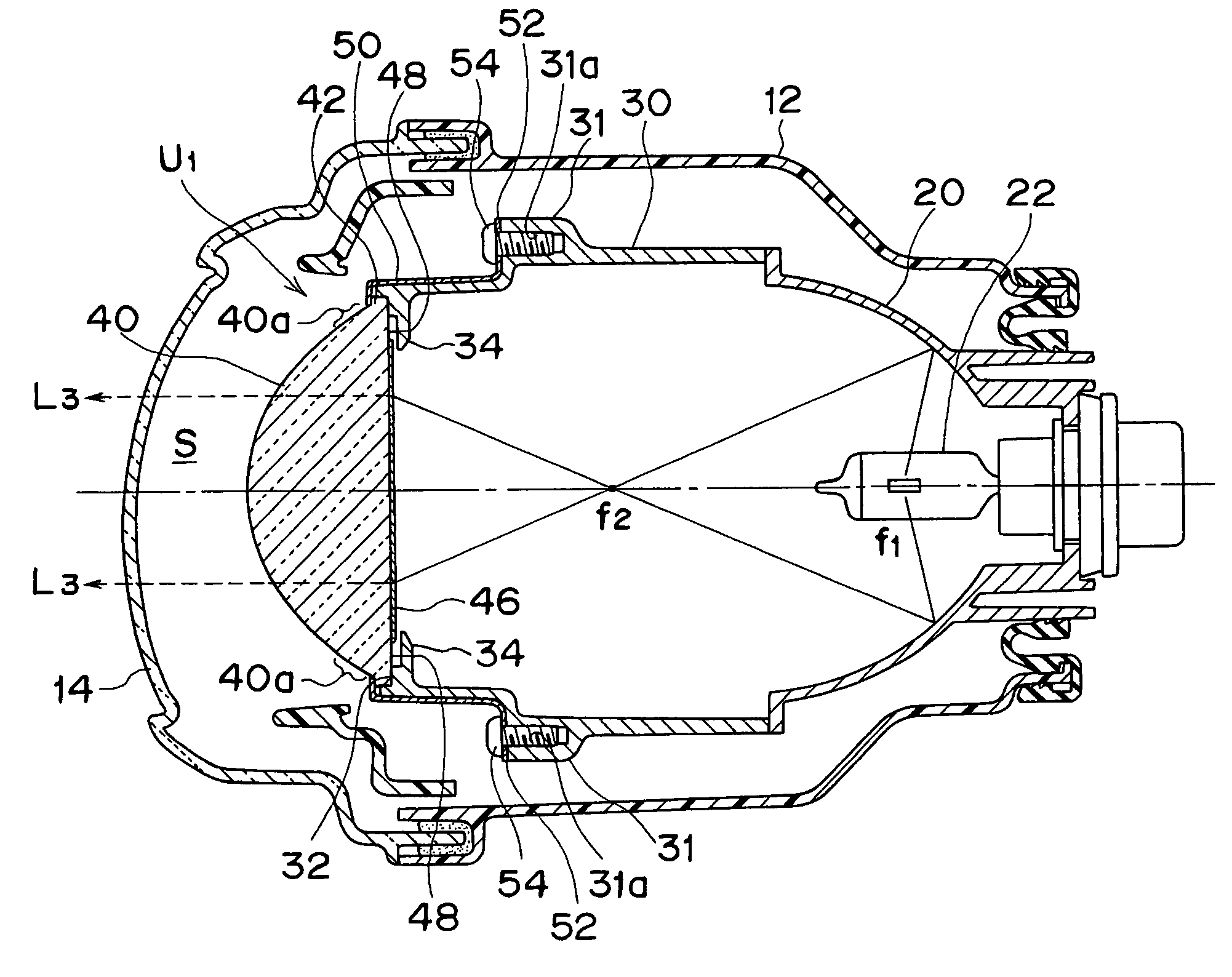
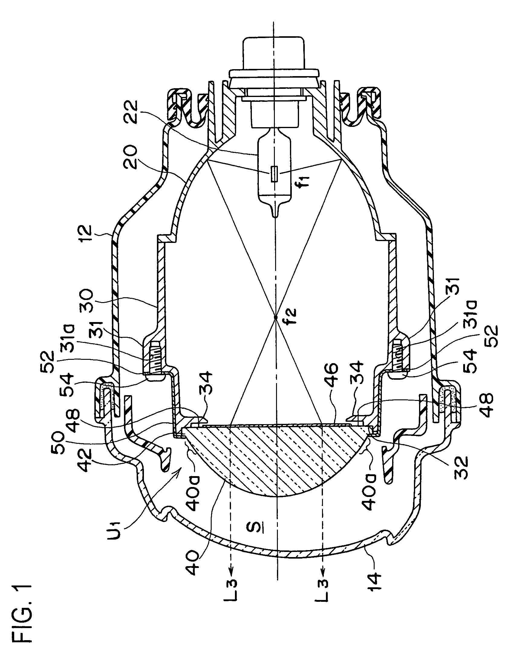
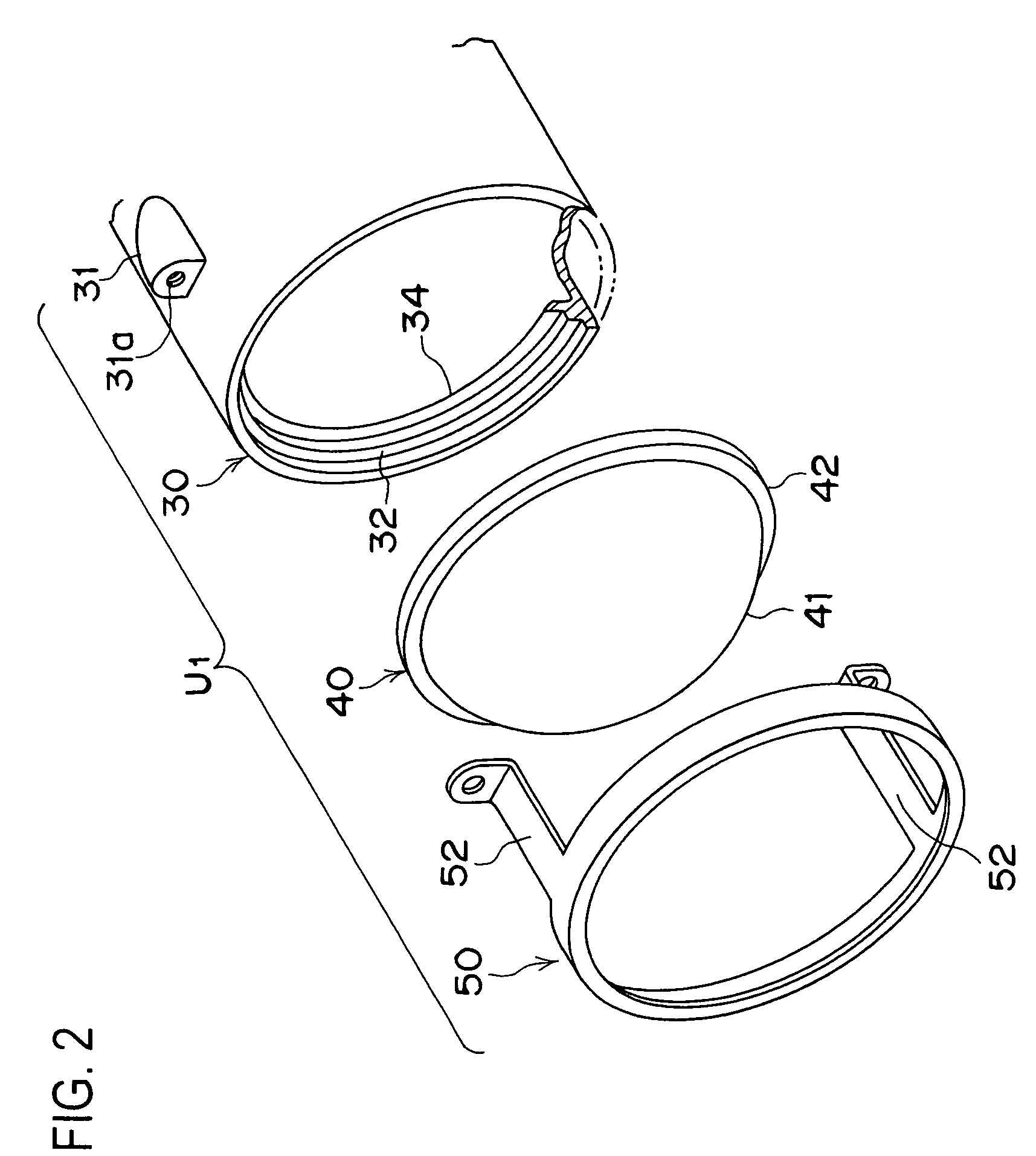
[0041]FIGS. 1, 2, 3A and 3B show an embodiment of an infrared light radiating lamp, suitable for application to a night forward visibility detection system which includes an infrared CCD camera, for example, mounted at an upper portion within the passenger compartment of the vehicle, which senses the field of vision in front of a vehicle. FIG. 1 is a longitudinal cross-sectional view of an infrared light radiating lamp according to the present invention, FIG. 2 is an exploded perspective view around a front end portion of a light source unit constituting a main portion of the lamp, and FIG. 3A and 3B are enlarged cross-sectional views around a lens engaging portion on a front edge portion of a lens holder of the lamp, of which FIG. 3A is an enlarged cross-sectional view of an end portion of a light shielding member of the lamp, and FIG. 3B is an enlarged cross-sectional view of an end portion of the light shielding member.

[0042]The night forward visibility detection system includes ...

second embodiment

[0052]FIG. 4 is an enlarged cross-sectional view (a view corresponding to FIG. 3A) showing the lens engaging portion on the front edge portion of the lens holder of the light source unit constituting a main portion of the infrared light radiating lamp according to the present invention.

[0053]In a light source unit U2 of the second embodiment, identical to the light source unit U1 of the first embodiment, an inner flange-shaped light shielding member 34A is provided around the inner side of the lens engaging portion 32 formed on a front edge portion of the lens holder 30 made of die-cast aluminum. An end face 34c extending in a ring shape in the circumferential direction with a predetermined width is formed on an extending end portion of the light shielding member 34A. However, the end face 34c is made non-reflective by a blackening treatment with black paint or the like, or provided with an alumite treatment or the like, so that light coming from the rear is not reflected toward the...

third embodiment

[0055]FIGS. 5 and 6 show an infrared light radiating lamp according to the present invention. FIG. 5 is a longitudinal cross-sectional view of the light source unit constituting a main portion of the lamp, and FIG. 6 is an exploded perspective view of a front end portion of the light source unit that constitutes a main portion of the lamp.

[0056]In the light source units of the above first and second embodiments the infrared light transmitting film 46 is formed directly on the convex lens 40; however, in the light source unit U3 of the third embodiment an infrared light transmitting filter 60 is disposed adjacent the rear of the convex lens 40.

[0057]Namely, the infrared light transmitting filter 60 is composed of the infrared light transmitting film 46 formed on a surface excluding a rim portion on a rear side of a transparent glass plate 61. Thus, a ring-shaped infrared light transmitting film-free region 48 with a predetermined width is provided on the rim portion of the infrared l...


PUM

PropertyMeasurementUnit
wavelengthaaaaaaaaaa
transparentaaaaaaaaaa
shapeaaaaaaaaaa

Abstract

An infrared light radiating lamp in which red light emitted from a front lens is diluted so as to become inconspicuous by emitting a small amount of visible light from a rim portion of a convex lens so that the lamp will not be mistaken for a tail lamp or a stop lamp and without causing glare. A vehicular infrared light radiating lamp is provided with a light source unit including a convex lens mounted via a lens holder forward of a reflector in which a light source is mounted. An infrared light transmitting film is provided on the rear surface of the convex lens. An infrared light transmitting film-free region is provided on the outer periphery of the infrared light transmitting film such that white visible light for diluting the red light emitted from the convex lens is emitted from the rim portion of the convex lens. Visible light with a high energy density is blocked by a light shielding member provided on the rear of the ring-shaped infrared light transmitting film-free region such that only visible light with a reduced energy density, namely, light dampened in intensity by reflection from the infrared light transmitting film, reaches the infrared light transmitting film-free region. Therefore, visible light emitted from the rim portion of the convex lens with an adjusted light intensity does not create glare.

Description

CROSS-REFERENCE TO RELATED APPLICATIONS[0001]Not applicableSTATEMENT REGARDING FEDERALLY SPONSORED RESEARCH OR DEVELOPMENT[0002]Not applicableREFERENCE TO SEQUENCE LISTING, A TABLE, OR A COMPUTER PROGRAM LISTING COMPACT DISK APPENDIX[0003]Not applicableBACKGROUND OF THE INVENTION[0004]The present invention relates to a vehicular infrared light radiating lamp intended to be mounted on a vehicle for radiating infrared light forward of the vehicle, and more particularly relates to a vehicular infrared light radiating lamp used in common with a CCD camera having up to a near-infrared sensitivity.[0005]A lamp of this type is constructed by arranging a visible light source and a parabolic reflector within a lamp chamber defined by a lamp body and a front lens. An infrared light transmitting filter, namely, a filter which reflects visible light components and transmits infrared light components, is formed over the entire surface of a glass plate disposed between the light source and the fr...

Claims


Application Information

Patent Timeline
Patent Type & Authority Patents(United States)
IPC IPC(8): B60Q1/00F21S8/10F21V5/00F21V9/04F21V17/00F21Y101/00G02B19/00
CPCF21S48/1136F21S48/1216G02B19/0028G02B19/009G02B19/0047F21S48/155F21S48/125F21V9/04F21S41/13F21S41/25F21S41/295F21S41/55F21V7/28
Inventor YAGI, SEIICHIROOKUI, KAZUKI
Owner KOITO MFG CO LTD
Why Eureka
Try Eureka