
Control device for positive displacement pumps

a technology of control device and positive displacement, which is applied in the direction of pumps, mechanical devices, liquid fuel engines, etc., can solve the problems of excessive increase in maximum pressure and risk of excessive delivery ra

Inactive Publication Date: 2006-06-13
ROBERT BOSCH AUTOMOTIVE STEERING
View PDF8 Cites 4 Cited by
  • Summary
  • Abstract
  • Description
  • Claims
  • Application Information

AI Technical Summary

Benefits of technology

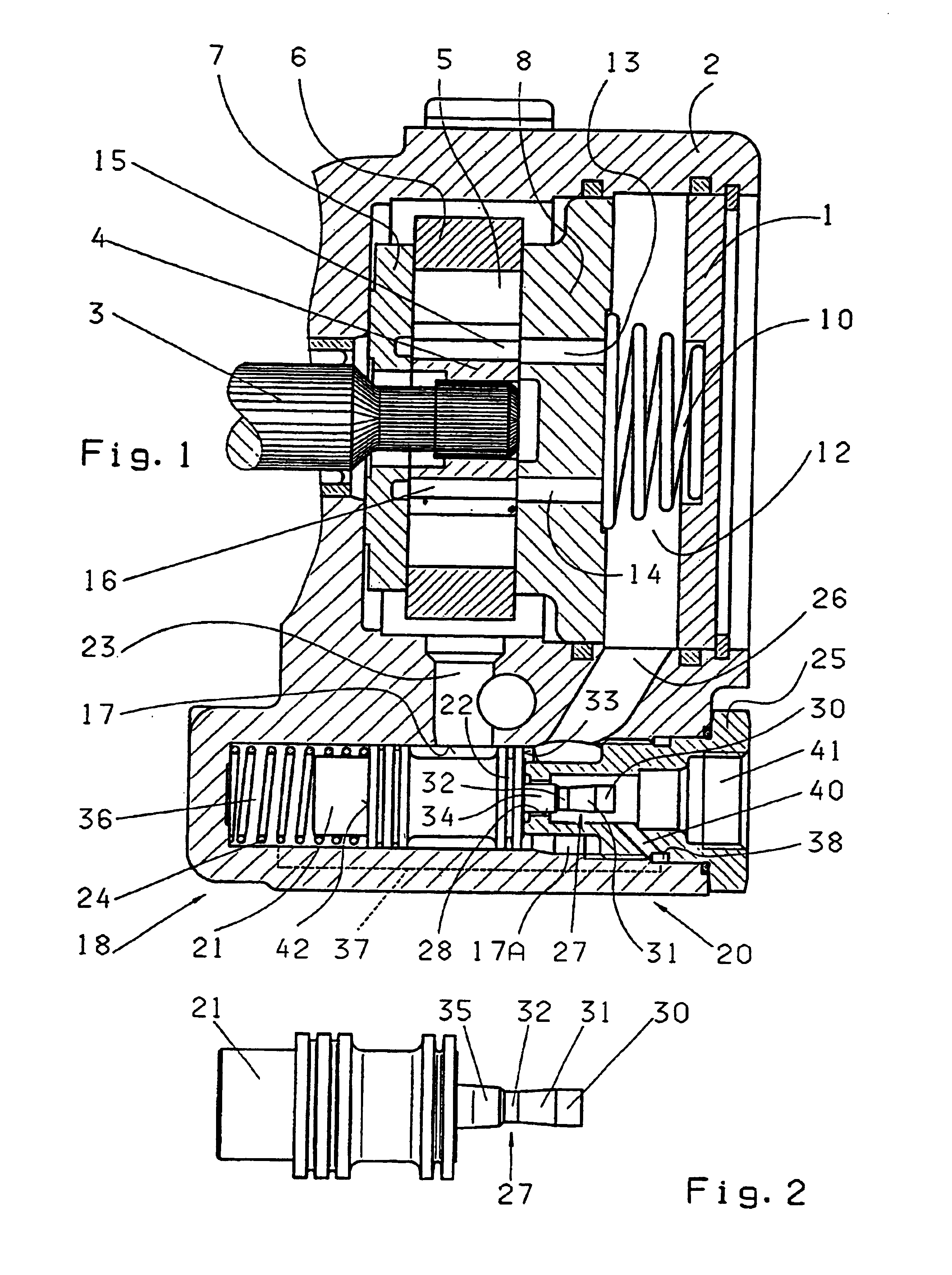
[0004]The above and other beneficial objects of the present invention are achieved by providing a control device as described herein by virtue of the fact that, in an axial. displacement region which, at the flow control piston, is not yet used for volume flow control, the control pin has a thickened portion, so that a minimal aperture cross-section exists in this displacement region. This results in the pressure difference across the thickened region being greater and the flow control piston moving earlier, or more rapidly in the case of dynamic operations.
[0005]Example embodiments of the present invention are described herein. The control pin with its thickened portion may be manufactured especially simply if the control pin is connected to the flow control piston and the throttling bore is fixed in relation to the housing, and the thickened portion is of cylindrical configuration. For better fine-adjustment of the control characteristic,-the thickened portion may have a frustoconical contour. In this connection, the larger diameter of the cone frustum may be arranged on the first end face of the flow control piston. In this manner, the characteristic of the control operation, the control speed, may be adjusted very finely.

Problems solved by technology

In such control devices, there is a risk of an excessive increase in delivery rate occurring when the pump undergoes a speed increase from the proportional range (for example no-load range) to the control range.
If an additional pressure-limiting valve is installed in such a control device, there is then moreover an excessive increase in maximum pressure when this pressure-limiting valve responds.

Method used


Image

  • Control device for positive displacement pumps

Examples


Embodiment Construction

[0009]A drive shaft 3 is mounted in a housing 2 closed by a cover 1.

[0010]In a conventional manner, the .drive shaft 3 bears a rotor 4 on splining.

[0011]Guided in radial slots of the rotor 4 are radially movable vanes 5 which slide sealingly along a cam ring 6. A pressure plate 7 bears sealingly against the pump assembly consisting of the rotor 4, the vanes 5 and the cam ring 6. A further pressure plate 8 bears against the pump assembly on the other side by virtue of the force of a spring 10. The vanes 5 enclose delivery chambers between them, which are connected to a suction connection. The pressure oil delivered emerges from the delivery chambers via pressure openings of the pressure plate 8 into a pressure chamber 12. The pressure chamber 12 has a connection to undervane spaces 15 and 16 via part-ring-shaped ducts 13 and 14. In this manner, it is possible to press the vanes 5 passing through the pressure zone at any one time outwardly into the cam ring 6.

[0012]In a housing bore 1...


PUM


Abstract

A control device for a positive displacement pump includes a throttle device and a flow control valve. The flow control valve includes a flow control piston and is configured to regulate an unrequired excess flow of the pump at an increased speed. The throttle device is configured to produce a speed-related pressure differential in a bore section, the pressure differential being responsible for the displacement of the flow control valve and the throttle device. The throttle device is arranged in the pressure outlet (bore section) of the pump and includes a regulating pin connected to the flow control piston, having a control contour configured so that a modifiable through cross-section is created in association with a throttle bore. The control pin has a wider section in an axial displacement area of the throttle device, the area not being involved in control of the volume flow, whereby a minimum obturating section arises in the displacement area. This may result in accelerated movement of the flow control piston, which may result in quicker reaction of the control mechanism, thereby preventing an overshoot and overincrease in the flow capacity.

Description

FIELD OF THE INVENTION[0001]The present invention relates to a control device for positive displacement pumps, e.g., for vane cell pumps. In this device, a pressure space is connected via a throttle device to an outlet connected to a consumer. A flow control piston is also provided, which is displaceable in a housing bore and the first end face of which has a connection to the pressure space. A second end face of the flow control piston projects into a chamber which is connected to the outlet downstream of the throttle device. Depending on a differential pressure acting on the two end faces, the flow control piston opens a connection from the pressure space to a pump inlet duct. The throttle device is located in the pressure output of the pump and includes a control pin, the control contour of which is configured so that, together with a throttling bore, a modifiable passage cross-section is brought about. In this connection, one of the two elements, control pin and throttling bore,...

Claims


Application Information

Patent Timeline
Patent Type & Authority Patents(United States)
IPC IPC(8): F04B49/00F04B39/10F04C2/344F04C14/26F04C15/00F04C15/06
CPCF04C14/26F04C15/062F04C15/00
Inventor DRASKOVITS, GUNTERZIMMERMANN, GERHARD
Owner ROBERT BOSCH AUTOMOTIVE STEERING
Learn More