End seal design for temperature sensing probes

a technology of end seals and temperature sensing probes, applied in the direction of ohmic-resistance waterproof/air-tight seals, instruments, heat measurement, etc., can solve the problems of environmental and/or mechanical damage, damage to the components of the temperature sensing probe is subject to mechanical stress

Inactive Publication Date: 2006-06-13
WATLOW ELECTRIC MFG
View PDF13 Cites 40 Cited by
  • Summary
  • Abstract
  • Description
  • Claims
  • Application Information

AI Technical Summary

Benefits of technology

[0011]According to yet another aspect of the invention, the invention is directed to a sheathed heater. The heater includes a generally tubular sheath having a closed end and a sealed end; a heater element disposed within the sheath; a conductor electrically coupled to the heater element, the conductor disposed at least partially in the sheath and having a portion extending out of the sheath through an opening defi

Problems solved by technology

Generally, the temperature sensing probe is subjected to harsh environments that easily can damage the components of the temperature sensing probe.
Furthermore, the temperature sensing probe is subject to mechanical stress due to vibration from surrounding machinery.
Although design safeguards have been implemented in probe construction, environmental and/or mechanical damage still may occur due to various circumstances.
For example, mechanical damage may occur to the electrical interface due to mechanical vibration and/or shock, causing fatigue and/or breakage of the electrical interface.
Mechanical damage also may occur due to

Method used


Image

  • End seal design for temperature sensing probes
  • End seal design for temperature sensing probes
  • End seal design for temperature sensing probes

Examples


Embodiment Construction

[0023]In the detailed description that follows, corresponding components have been given the same reference numerals, regardless of whether they are shown in different embodiments of the present. To illustrate the present invention in a clear and concise manner, the drawings may not necessarily be to scale. Also, some features may be shown schematically.

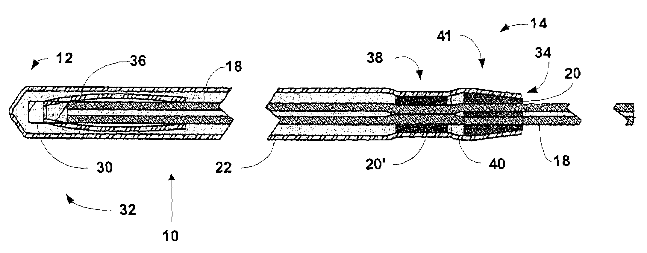
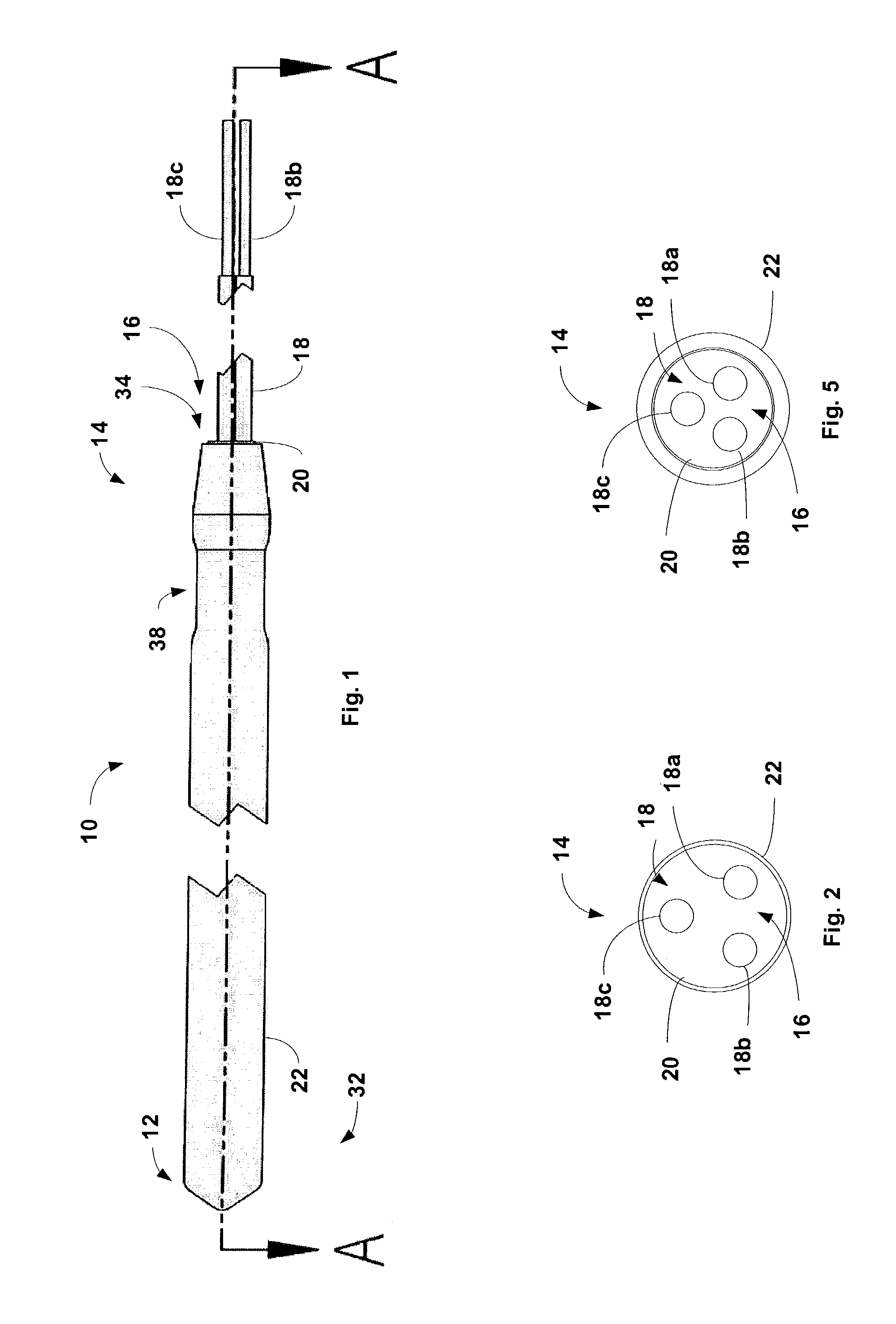
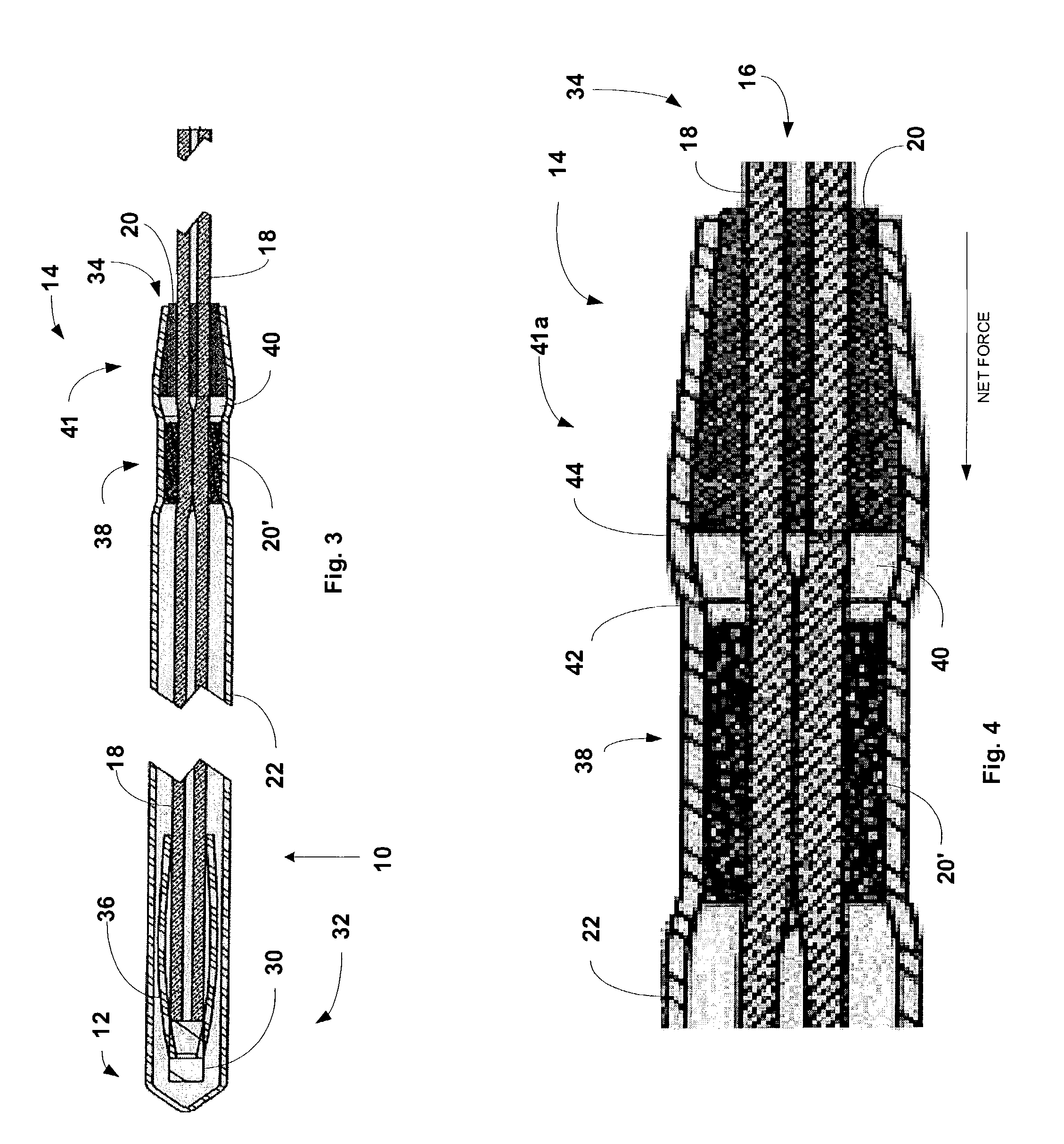
[0024]Referring to FIG. 1, a temperature sensing probe 10 in accordance with the present invention is illustrated. One end of the temperature sensing probe 10 may be referred to as a hot end 12, which typically is inserted into a media for temperature measurement. The other end of the temperature sensing probe 10 may be referred to as the cold end 14. Although not illustrated, the cold end 14 can optionally be mounted to a fixed structure. For example, the cold end 14 may be attached to a rubber grommet, a compression fitting or a welded fitting, each of which may be mechanically attached to the fixed structure.

[0025]In the illustrat...


PUM


Abstract

An end seal for a temperature sensing probe. Electrical interface wiring is passed through a restraining element and is operatively coupled to a temperature sensing element or heater element mounted in the sheath. The sheath is formed around the restraining element in a shape that provides a net force inward as temperature variations expand and contract the restraining element.

Description

FIELD OF THE INVENTION[0001]The present invention relates to an improved end seal configuration adapted for use with temperature sensing probes and sheathed heaters.BACKGROUND[0002]Temperature sensing probes, such as thermistors, resistance temperature detectors (RTD's) and resistance thermometers are used in a wide array of applications to provide temperature feedback of various media. In particular, temperature sensing probes are used in industrial process control, engine control, and the like, to measure the temperature of a process or device and provide the measured temperature to a remote device, such as a PID controller, for example. In response to the temperature feedback from the probe, the PID controller may alter system parameters to maintain and / or regulate the temperature of the process or device. Additionally, the temperature feedback from the probe may be used to alarm abnormal conditions (e.g., an over temperature warning).[0003]Temperature sensing probes have what is...

Claims


Application Information

Patent Timeline
IPC IPC(8): H05B3/06
CPCG01K7/22H05B3/06H05B3/04G01K2007/163
Inventor DAVIS, WAYNERIBICH, PAULHARVEY, DANKASAM, NAWAZ
Owner WATLOW ELECTRIC MFG
Why Eureka
Try Eureka