Rotary electrical machines

Inactive Publication Date: 2006-06-13
GE POWER CONVERSION
View PDF16 Cites 24 Cited by
  • Summary
  • Abstract
  • Description
  • Claims
  • Application Information

AI Technical Summary

Benefits of technology

[0043]An important alternative avoids the use of coil-type windings and instead uses a set of single straight conductors passing from one end of the stator to the other. The single conductors may be connected to a switching assembly at one end only or at b

Problems solved by technology

This connection process is costly and time consuming.
A problem with prior art machines of this type arises if a short circuit occurs across the windings, or a wire inside a winding breaks, giving an open circuit.
Short-circuiting can also occur due to faults external to the windings.
When a short circuit fault arises the machine may need to be stopped to permit removal of the short circuit, since a closed loop around a winding will generate an undesirable braking torque

Method used


Image

  • Rotary electrical machines
  • Rotary electrical machines
  • Rotary electrical machines

Examples


Embodiment Construction

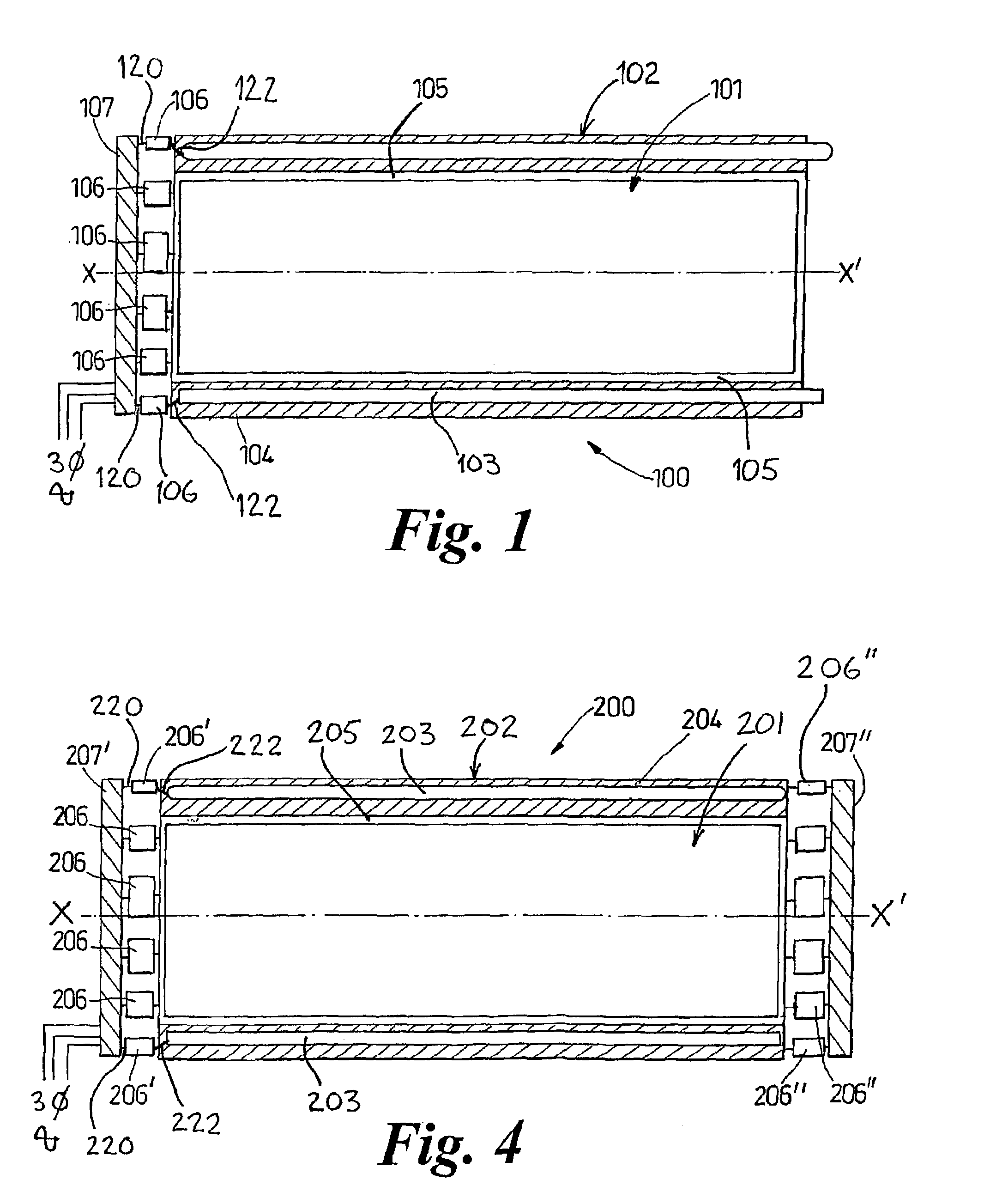
[0064]The electrical machine illustrated in FIG. 1 of the accompanying drawings comprises an AC induction motor assembly 100. The assembly 100 includes a central rotor 101 which as known is supported at its axially opposed ends for rotation about an axis XX′ by means of bearings on a central shaft (not shown). A stator 102 surrounds the rotor 101 and comprises a former 104 for receiving and holding the field-generating conductors 103. The former 104 is a generally elongate tubular structure so that the inside of the tube accommodates the rotor 101. A small air gap 105 is provided between the rotor 101 and the former 104.

[0065]The former 104 includes a plurality of grooves or slots which extend in a known manner axially from one end of the former 104 to the other. In the present embodiment, each slot accommodates a field-generating conductor 103 which takes the form of a field winding. The cross-sectional view of FIG. 1 shows only two diametrically opposed field-generating conductors...


PUM


Abstract

An electrical machine, such as an induction motor, comprises a stator having a plurality of conductive windings spaced around an axis of rotation, a rotor rotatable about the axis of rotation in response to the flow of current through the stator windings, and a plurality of switching assemblies provided at circumferentially spaced locations around the stator. Each switching assembly is electrically connected between an end of at least one of the windings and a power supply busbar ring assembly comprising at least one conductor. The busbar assembly connects the electrical supply to one or more of the switching assemblies, each of the switching assemblies being effective to selectively control the supply of current to at least one of the windings.

Description

FIELD OF THE INVENTION[0001]This invention relates to improvements in rotary electrical machines, and in particular but not exclusively to a rotary machine such as an electric motor or generator with integral control circuitry.BACKGROUND OF THE INVENTION[0002]Rotary machines are widely used in industrial applications for converting electrical energy into rotational movement (in the case of a motor) or for producing electrical energy from rotational movement (in the case of a generator). To a large extent the requirements for the design of electric motors and generators are the same and so only the case of electric motors will be described in detail hereinafter.[0003]Many applications require the provision of a variable-speed rotary machine. Although a large number of different types of electrical machine are known, the most widely used motor type for high power applications are AC synchronous and AC induction motors. Both AC synchronous and AC induction motors comprise a central rot...

Claims


Application Information

Patent Timeline
IPC IPC(8): H02K11/00H02K3/04H02K3/24H02K3/28H02K3/50H02K9/19H02K11/04
CPCH02K3/28H02K11/0073H02K2203/09H02K11/33
Inventor CRANE, ALLAN DAVID
Owner GE POWER CONVERSION
Why Eureka
Try Eureka