Battery monitoring system and method

a battery monitoring and battery technology, applied in battery/fuel cell control arrangement, secondary cell servicing/maintenance, instruments, etc., can solve the problems of increased cranking time, battery may require replacement,

Active Publication Date: 2006-06-13
CPS TECH HLDG LLC
View PDF143 Cites 106 Cited by
  • Summary
  • Abstract
  • Description
  • Claims
  • Application Information

AI Technical Summary

Problems solved by technology

However, such known systems have several disadvantages including that the battery may require replacement before such pre-selected time, and any perceived increase in the cranking time may be due to other factors unrelated to the battery (such as a faulty starter).
However, such known systems have several disadvantages, including that they do not record the “history” of the battery during its use as would allow for a more accurate prediction of the capacity of the battery, notwithstanding the measured voltage.

Method used


Image

  • Battery monitoring system and method
  • Battery monitoring system and method
  • Battery monitoring system and method

Examples


Embodiment Construction

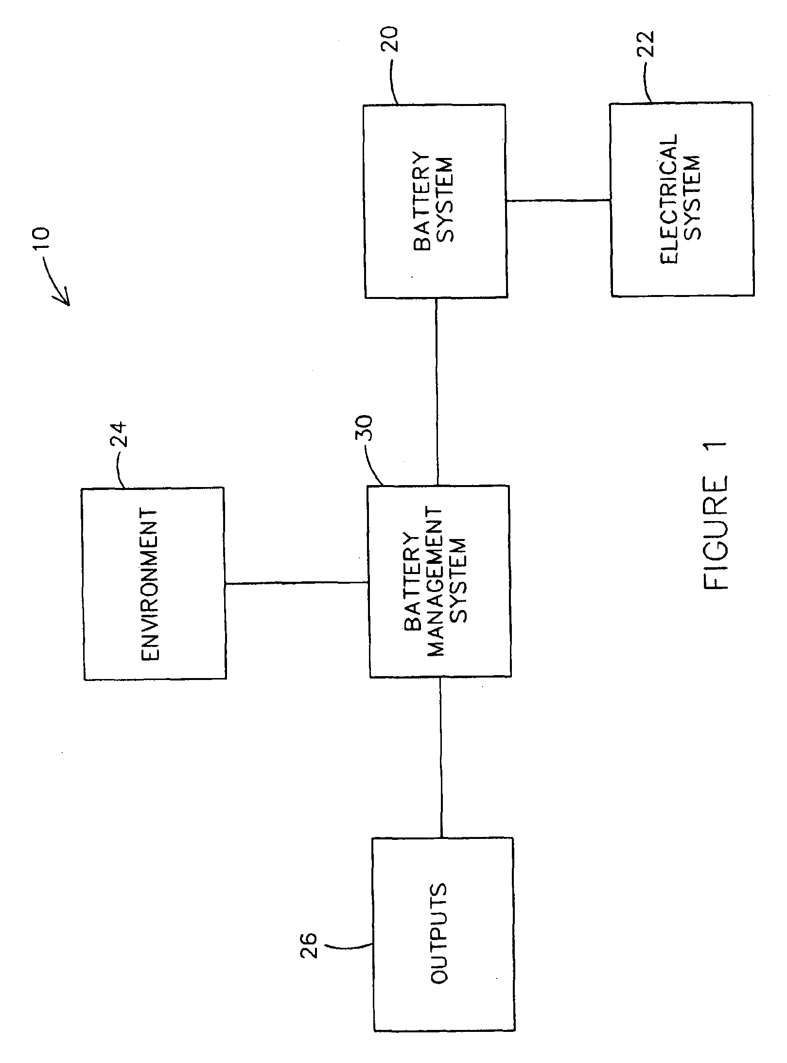
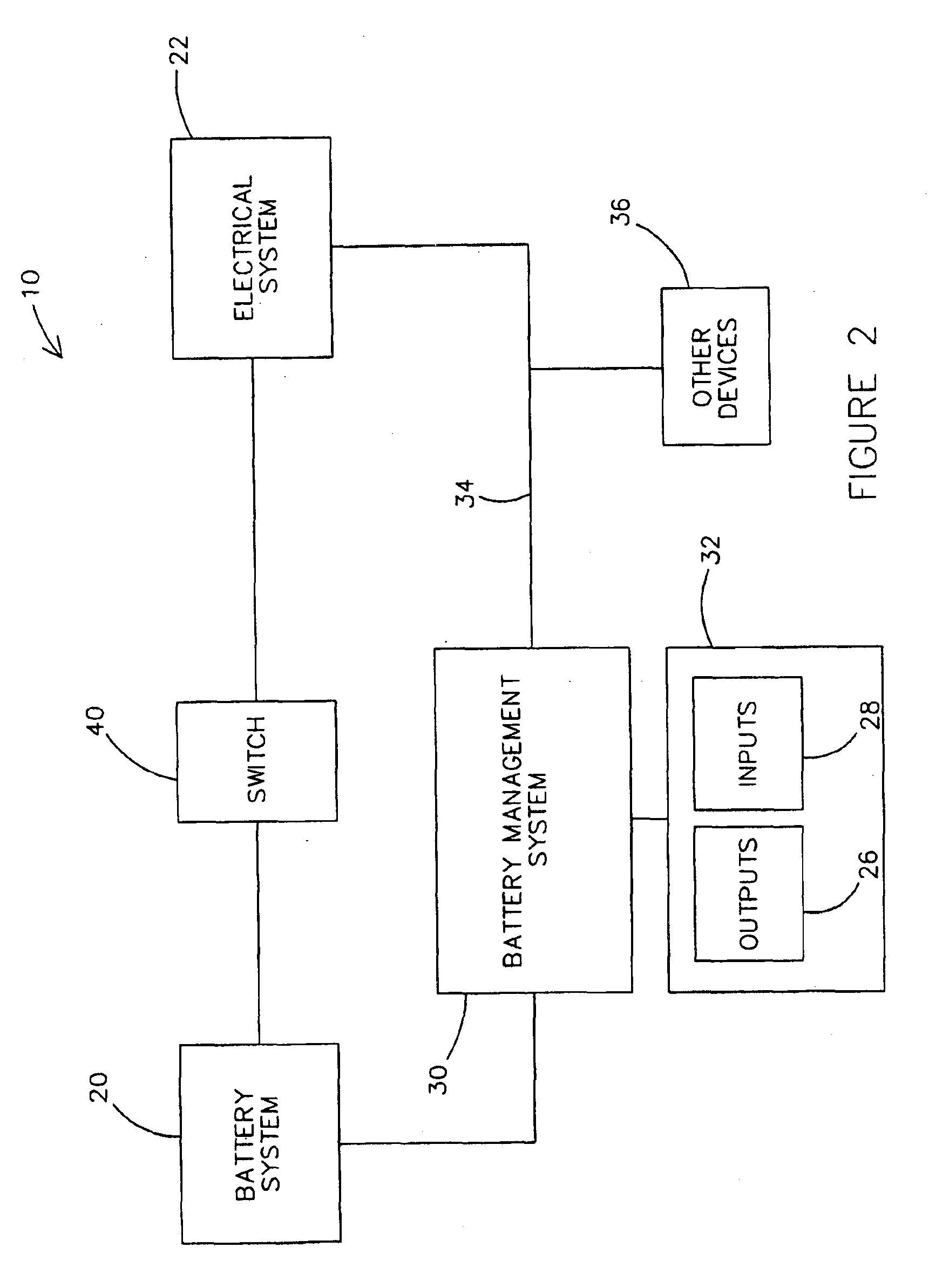
[0017]A battery monitoring system 10 as shown in FIG. 1 measures and records a set of parameters of a battery system 20 periodically during use over time. The parameters such as the voltage, temperature, state of charge and cycling of the battery may be acquired by a battery management system 30 from battery system 20, a vehicle electrical system 22, and an environment 24 according to a preferred embodiment, or may be otherwise acquired according to alternative embodiments.

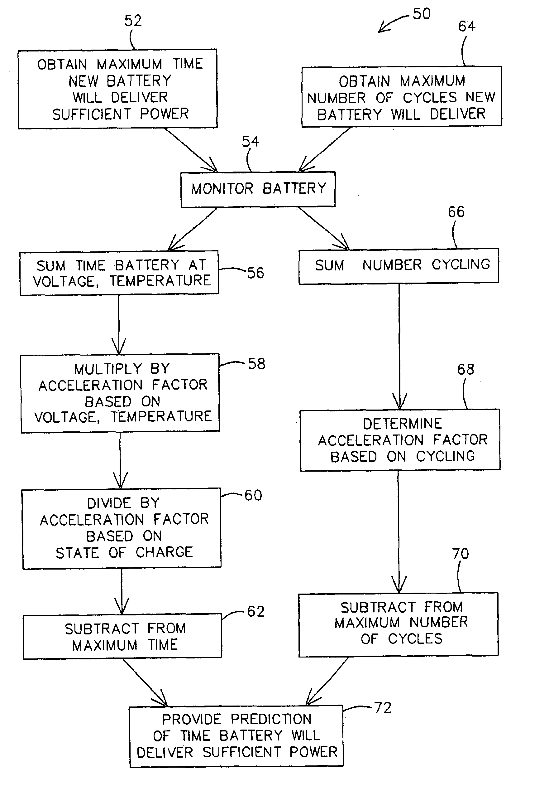
[0018]System 10 predicts the ability of battery system 20 to perform in certain applications as expected in the future. Specifically, system 10 predicts whether battery system 20 has a sufficient remaining amount of “life” (i.e. may deliver a sufficient amount of power to the vehicle for a sufficient amount of time). In other words, system 10 predicts whether battery system 20 will likely be able to start the engine of the vehicle and power the loads of the vehicle.

[0019]A new, fully charged battery of battery sys...


PUM

PropertyMeasurementUnit
timeaaaaaaaaaa
voltageaaaaaaaaaa
voltageaaaaaaaaaa

Abstract

A method for predicting the remaining life of a battery for a vehicle includes obtaining a value representative of the amount of remaining life for a battery in a new and fully charged state and monitoring at least one parameter of the battery during use of the battery. The method also includes obtaining an acceleration factor based on the at least one monitored parameter and estimating the amount of life lost from the battery utilizing the acceleration factor.

Description

CROSS-REFERENCE TO RELATED APPLICATIONS[0001]This application is a continuation under 35 U.S.C. § 120 of U.S. patent application Ser. No. 10 / 313,983 titled “Battery Monitoring System” filed on Dec. 6, 2002, now U.S. Pat. No. 6,727,708 which claims the benefit of priority as available under 35 U.S.C. § 119(e) to U.S. Provisional Patent Application No. 60 / 337,183 titled “Battery Monitoring System and Method” filed Dec. 6, 2001.[0002]The disclosures of the following patent applications are hereby incorporated by reference in their entirety: U.S. patent application Ser. No. 10 / 313,983 titled “Battery Monitoring System” filed on Dec. 6, 2002 and U.S. Provisional Patent Application No. 60 / 337,183 titled “Battery Monitoring System and Method” filed Dec. 6, 2001.FIELD[0003]The present invention relates to a battery monitoring system and method. The present invention more specifically relates to a system and method for predicting whether the battery will perform in certain applications as ex...

Claims


Application Information

Patent Timeline
Patent Type & Authority Patents(United States)
IPC IPC(8): G01N27/416G01R31/36H01M10/42H01M10/44H02J7/00
CPCG01R31/36H01M10/44H02J7/0047B60L11/14B60L11/1857B60L11/1861H01M10/4257Y02T10/70Y02T10/7077Y02T10/7044Y02T10/7005Y02T10/705B60L2240/545B60L2240/547B60L2240/549B60L2240/80B60L50/16B60L58/16B60L58/12Y02T10/7072Y02E60/10H02J7/0048H02J7/005
Inventor DOUGHERTY, THOMAS J.WRUCK, WILLIAM J.MILES, RONALD C.CHEN, DEEYU C.THOMPSON, MICHAEL L.
Owner CPS TECH HLDG LLC
Why Eureka
Try Eureka