Method and apparatus for controlling temperature gradients within a structure being cooled

a technology of temperature gradient and structure, applied in the field of cooling techniques, can solve the problems of mechanical pump reliability concerns, undesirable phase characteristics of different circuit portions, and inability to distribute heat in the transverse direction

Active Publication Date: 2006-06-13
RAYTHEON CO
View PDF4 Cites 62 Cited by
  • Summary
  • Abstract
  • Description
  • Claims
  • Application Information

AI Technical Summary

Problems solved by technology

Variations in the phase characteristics of the different circuit portions are undesirable, because such variations can introduce distortion into transmitted wavefronts and received wavefronts.
However, mechanically pumping these coolants requires an external source of energy to drive the pump, and the use of a mechanical pump presents reliability concerns as a result of the possibility of a mechanical failure.
In particular, a layer of parallel heat pipes can be provided to transport high heat fluxes in directions parallel to the heat pipes, but it is not possible to distribute heat in a transverse direction without adding a second layer of heat pipes that extends transversely to the first layer.
The second layer of heat pipes increases the size and weight of the system, and is not as effective as the first layer in distributing heat, due to the conductive resistance between the two layers of heat pipes.
In a phased array antenna system in which the circuitry is provided in a configuration commonly known as a slat architecture, the use of even a single layer of heat pipes may be difficult or impossible, due to dimensional limitations inherent in the system.

Method used


Image

  • Method and apparatus for controlling temperature gradients within a structure being cooled
  • Method and apparatus for controlling temperature gradients within a structure being cooled
  • Method and apparatus for controlling temperature gradients within a structure being cooled

Examples


Embodiment Construction

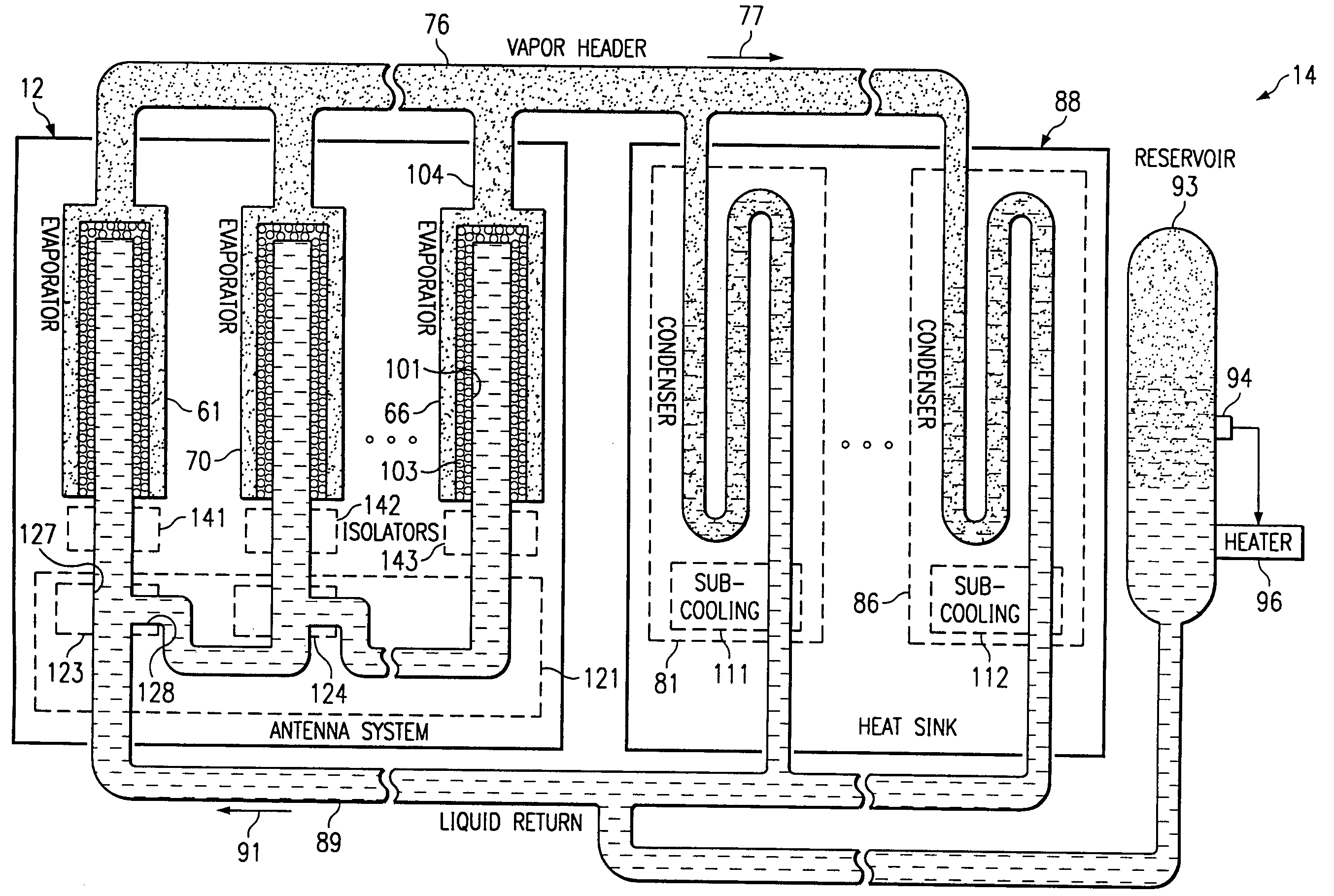
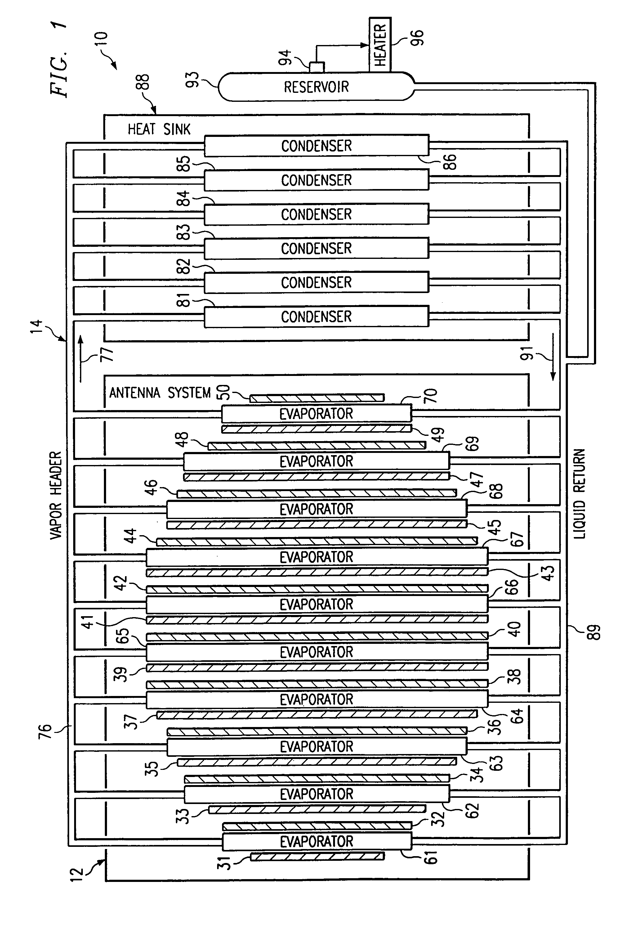
[0017]FIG. 1 is a block diagram of an apparatus 10 which embodies aspects of the present invention. In the disclosed embodiment, the apparatus 10 is configured for use in a satellite, but the present invention can be used in a wide variety of contexts other than a space vehicle. The apparatus 10 includes a phased array antenna system 12 and a cooling system 14 for the antenna system, at least part of the cooling system 14 being disposed within the antenna system 12.

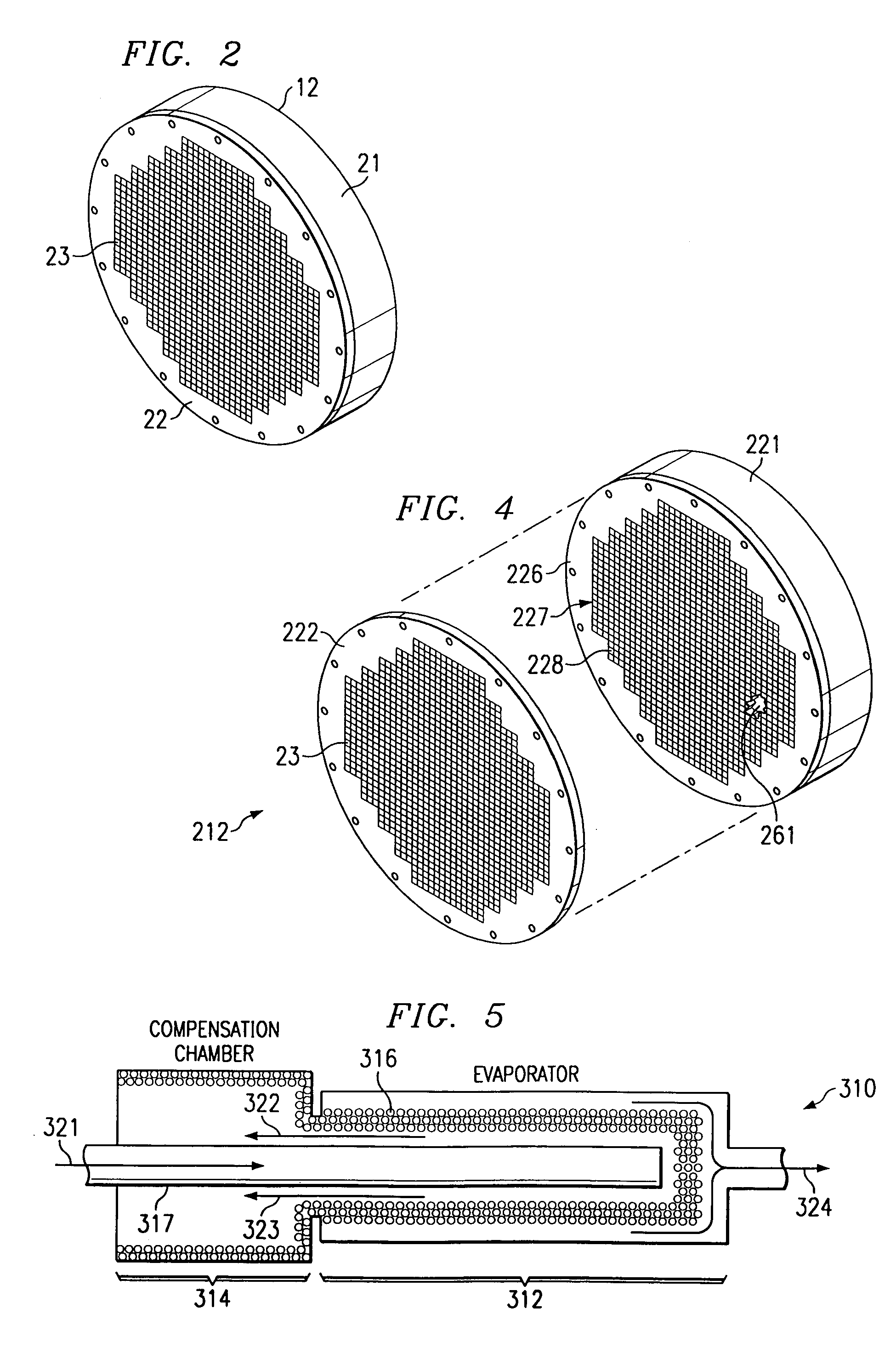
[0018]FIG. 2 is a diagrammatic perspective view of the phased array antenna system 12. The antenna system 12 includes a housing 21 having on one side thereof a planar wall 22, and includes a plurality of antenna elements 23 which are provided on the wall 22. The antenna elements 23 are arranged in an approximately circular array which includes a plurality of parallel columns and a plurality of parallel rows, the rows extending perpendicular to the columns. The antenna system 12 includes circuitry which is not visible in F...


PUM


Abstract

A phased array antenna apparatus has a plurality of circuit portions which are each coupled to a respective antenna element. Capillary pressure of a cooling fluid within a wick in a loop is utilized to urge the fluid to travel around the loop, the wick being disposed in the region of the circuitry. In a variation, there are plural wicks in respective evaporators, and cooling fluid is distributed among the evaporators through a series of T-junctions. In another variation, cooling fluid is distributed to a plurality of evaporators in a sequence corresponding to a progressive increase in the respective amounts of heat accepted by the evaporators from structure being cooled.

Description

[0001]This application claims the priority under 35 U.S.C. §119 of provisional application No. 60 / 421,373 filed Oct. 24, 2002.TECHNICAL FIELD OF THE INVENTION[0002]This invention relates in general to cooling techniques and, more particularly, to cooling techniques which facilitate control of temperatures and temperature gradients within a structure being cooled.BACKGROUND OF THE INVENTION[0003]There are a variety of types of applications in which there is a need to control temperatures and / or temperature gradients within a structure being cooled. One example is phased array antenna systems, which are used in a number of different contexts, such as satellites and other space vehicles. A phased array antenna system includes an array of antenna elements that are separately controlled by respective circuit portions. Wavefronts transmitted and received by the antenna system are represented electrically by respective signals at the various antenna elements, and these electrical signals h...

Claims


Application Information

Patent Timeline
Patent Type & Authority Patents(United States)
IPC IPC(8): H01Q21/00
CPCH01Q1/02F28D15/06H01Q21/00
Inventor SHORT, JR., BYRON ELLIOTTOCHTERBECK, JAY M.
Owner RAYTHEON CO
Why Eureka
Try Eureka