User-interface and method for curved multi-planar reformatting of three-dimensional volume data sets

a multi-planar, user-interface technology, applied in the field of user-interface and user-interface for curved multi-planar reformatting of three-dimensional volume data sets, can solve the problems of not being able to fully show in a single, arise for other curved anatomical structures, and can not be used in a single, so as to improve the ease of use, simplify the interface, and improve the flexibility of the mpr process

Inactive Publication Date: 2006-06-13
TOSHIBA MEDICAL VISUALIZATION SYST EURO
View PDF8 Cites 26 Cited by
  • Summary
  • Abstract
  • Description
  • Claims
  • Application Information

AI Technical Summary

Benefits of technology

[0015]This combination of features provides an efficient and straightforward user interface for a curve-related MPR system, which gives the user effective access to powerful curved MPR techniques without the need for understanding of the complex underlying spatial and numerical concepts involved in curve-related MPR processes. The interface allows curve-related MPR to be used in a highly flexible manner, because the user has a high level of input relating to the geometry and orientation of the images and the positioning of the curve. The icons allow the user to completely specify the orientation of the curve, so that subsequent image processing and display is performed in the appropriate geometrical context. Also, the provision of three standard orthogonal MPR images at all times allows the user to define the curve in three dimensions with great precision. It enables the user to reshape the curve after definition if the resulting MPR image requires modification, or to compare one or more MPR views. These features remove the requirement for any assumptions to be made in the calculation, derivation and display of the MPR image. Thus the displayed image accurately reflects those anatomical features in the correct orientation that the user desires to observe. Moreover, the user can be confident that this is the case, because he has input all the variables, and knows that no assumptions are being made. Thus a precise and accurate medical opinion can be reached on the basis of the displayed image. This results in improved patient treatment, because medical complaints can be treated appropriately and effectively. Health care costs can also be reduced, because better patient treatment results in faster recovery times and reduced rate of readmission to hospital. This is in contrast with previous MPR systems in which user input is less and assumptions are necessary, which can generate confusing images with orientations which are difficult to determine. In some cases, it may not be apparent to the user that the image is not the desired image, so that diagnostic and / or treatment decisions are made without the knowledge that a margin of error should be included.
[0036]Picture Archiving and Communication Systems (PACS) are being widely introduced into hospitals at the present time, as a convenient way of storing and accessing patient images. MPR can be performed on any image which is stored as a three-dimensional volume data set, so it is advantageous to provide the user interface of the present invention for with an MPR system which is used in conjunction with a PACS arrangement.

Problems solved by technology

However, a typical volume data set will contain details of many body parts which are not relevant for a particular study, or which obscure important features.
However, the anatomical feature of interest is almost always non-planar, so cannot be shown fully in a single slice.
The same problem arises for other curved anatomical structures, such as bronchi, the colon, the spine, and dental structures.
However, in some circumstances, the assumptions made may be inaccurate or wholly incorrect.
This is clearly undesirable.
Worse, though, is that there may be instances when the user fails to identify any problem.
This can lead to erroneous clinical decisions being made, which puts patients at risk.
This is limiting, in that if the curve is particularly tortuous, the user is unable to place curve points in the centre of the curve path, so that the resulting curve and curved MPR image may not accurately reflect the user's desired view.
The two non-selected images are also no longer available to use as references to determine curve orientation when the user becomes disoriented.
However, the user has only minimal control of a chosen curved sheet, and therefore can be easily confused about the orientation of the curve.

Method used


Image

  • User-interface and method for curved multi-planar reformatting of three-dimensional volume data sets
  • User-interface and method for curved multi-planar reformatting of three-dimensional volume data sets
  • User-interface and method for curved multi-planar reformatting of three-dimensional volume data sets

Examples


first embodiment

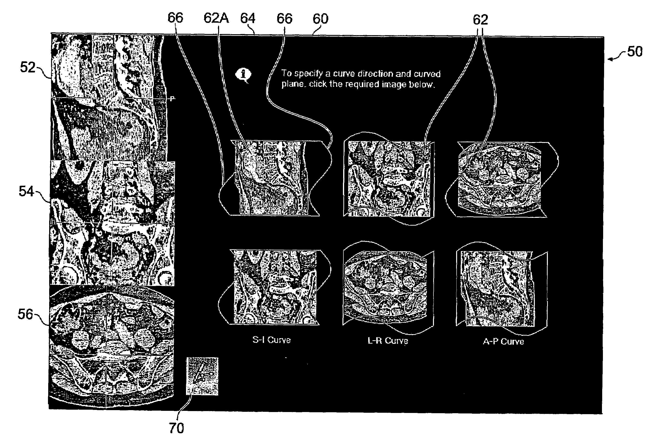
[0082]As is evident from the foregoing description of curved MPR, there are many variables which affect the final curved MPR image displayed to the viewer. These include the shape of the curve, the tracking MPR plane, the primary direction of the curve, the MPR plane “to be curved”, and the extrusion direction. The embodiments of the present invention seek to provide the user with as much flexibility in selecting and modifying these variables as possible while maintaining an easy-to-understand user interface. This allows the user to be confident that the final curved MPR image depicts the relevant parts of the patient, so that accurate clinical decisions can be based thereon.

[0083]Thus the present invention is concerned with the user interface of a computer implemented curved MPR image processing package. It provides the user with the ability to make a range of choices, and to modify the choices after generation of the MPR image. This is in contrast with prior art systems, which all...

second embodiment

[0100]The user interface of the first embodiment can be modified for display of cross-curve MPR views. To generate a cross-curve MPR view, it is only necessary to specify the primary direction of the curve. There is no “curving” carried out, so there is no need to select a MPR view “to be curved”. Consequently, there are only three possible options to choose between, instead of the six required for a curved MPR view.

[0101]Each of the three choices are of the form “the primary direction of the curve is along the Foo axis—i.e. the Foo MPR is the tracking MPR”, where Foo is a standard axis. The choice is expressed as “Create a Foo curve”. The choices therefore are:

[0102]Create a Transverse curve

[0103]Create a Coronal curve

[0104]Create a Sagittal curve

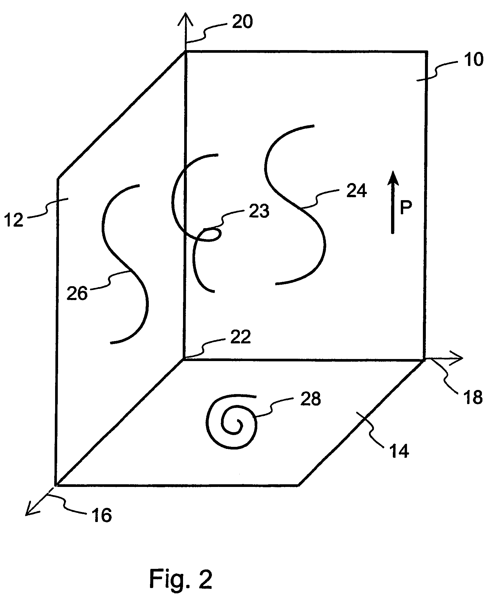
[0105]In the second embodiment, each choice is represented by a pair of icons, showing the two non-Foo MPR views adorned with a generic curved line or lines to represent the Foo curve. Thus six icons are again provided, and may be the same...

third embodiment

[0108]A user interface for cross-curve MPR can alternatively have three icons instead of six icons linked in pairs, since the choice of the user is limited to the selection of one of three directions for the curve. Hence one selectable icon is provided on the interface for each of the three directions. Once again, thumbnail versions of the standard planar MPR images can be used. However, in this embodiment, the thumbnail shows the tracking MPR plane, instead of the MPR plane which is to be curved. There is no requirement for any curved lines to be overlaid on the icons, because the MPR images shown are not going to be curved, and the curve itself is going to be roughly normal to the image. Thus the information suggested by the curved lines of the first and second embodiments is not relevant.

[0109]FIG. 7(b) shows a user interface 200 with icons of this type. As before, the user interface 200 has first, second and third display areas 202, 204, 206 in which are displayed three orthogon...


PUM


Abstract

A user interface for a computer-implemented Multi-Planar Reformatting (MPR) system comprises three display areas in which are displayed three orthogonal MPR images of the volume data set; a curve drawing tool to allow a user to define a curve through the volume data set; six selectable icons each representing one of six possible combinations of a plane parallel to one of the orthogonal MPR images and a direction substantially normal to a plane parallel to one of the other two MPR images, using which the user selects an approximate direction for the curve; and a fourth display area displaying a curve-related MPR image related to one or more points along the curve. The icons may be individually selectable to allow user input of adequate orientational information for a curved MPR image, or selectable in pairs for input of directional information for a cross-curve MPR image. Alternatively, three icons may be provided for a cross-curve MPR system. A tool to allow rotation of a curved MPR image about the curve can be provided, as can visual indicators of the depth of the curve within the volume, and of the orientation of the cross-curve image.

Description

[0001]This application is a national phase of International Application No. PCT / GB2003 / 003997 filed Sep. 16, 2003 and published in the English language.BACKGROUND OF THE INVENTION[0002]The present invention relates to curved multi-planar reformatting of three-dimensional volume data sets, particularly volume data sets representing patient images, and user interfaces for computer-implemented curved multi-planar reformatting systems.[0003]Modern patient imaging methods, such as computed tomography (CT) and magnetic resonance imaging (MRI), generate large three-dimensional volume data sets representing the patient's body. These volume data sets are highly detailed and allow complex studies of the body to be made. However, a typical volume data set will contain details of many body parts which are not relevant for a particular study, or which obscure important features. Data processing methods are hence used to manipulate the data set and present a viewer with an image which shows the i...

Claims


Application Information

Patent Timeline
Patent Type & Authority Patents(United States)
IPC IPC(8): G06T17/00G06T19/00
CPCG06T3/0037G06T19/00G06T15/08G06T2219/028G06T2210/41G06T2219/008
Inventor BAILEY, ANTHONYBARISH, MATTHEW
Owner TOSHIBA MEDICAL VISUALIZATION SYST EURO
Why Eureka
Try Eureka