Filter device

a filter device and video signal technology, applied in the field of video signal filtering, can solve the problems of reducing circuitry space and reducing circuitry energy consumption, and achieve the effects of reducing costs, comparing the performance of such a 3-d comb filter, and significantly reducing the space needed for circuitry

Inactive Publication Date: 2006-06-13
FUNAI ELECTRIC CO LTD
View PDF5 Cites 13 Cited by
  • Summary
  • Abstract
  • Description
  • Claims
  • Application Information

AI Technical Summary

Benefits of technology

[0010]The main object of the present invention is to provide a 3-D comb filter of which the costs are significantly reduced as compared to currently available 3-D comb filters, while, further, the performance of such a 3-D comb filter is comparable or even improved as compared to currently available 3-D comb filters.

Problems solved by technology

Furthermore, implementing part of the filter device in software instead of hardware reduces the space needed for circuitry and reduces the energy consumed by circuitry.

Method used


Image

  • Filter device
  • Filter device
  • Filter device

Examples


Embodiment Construction

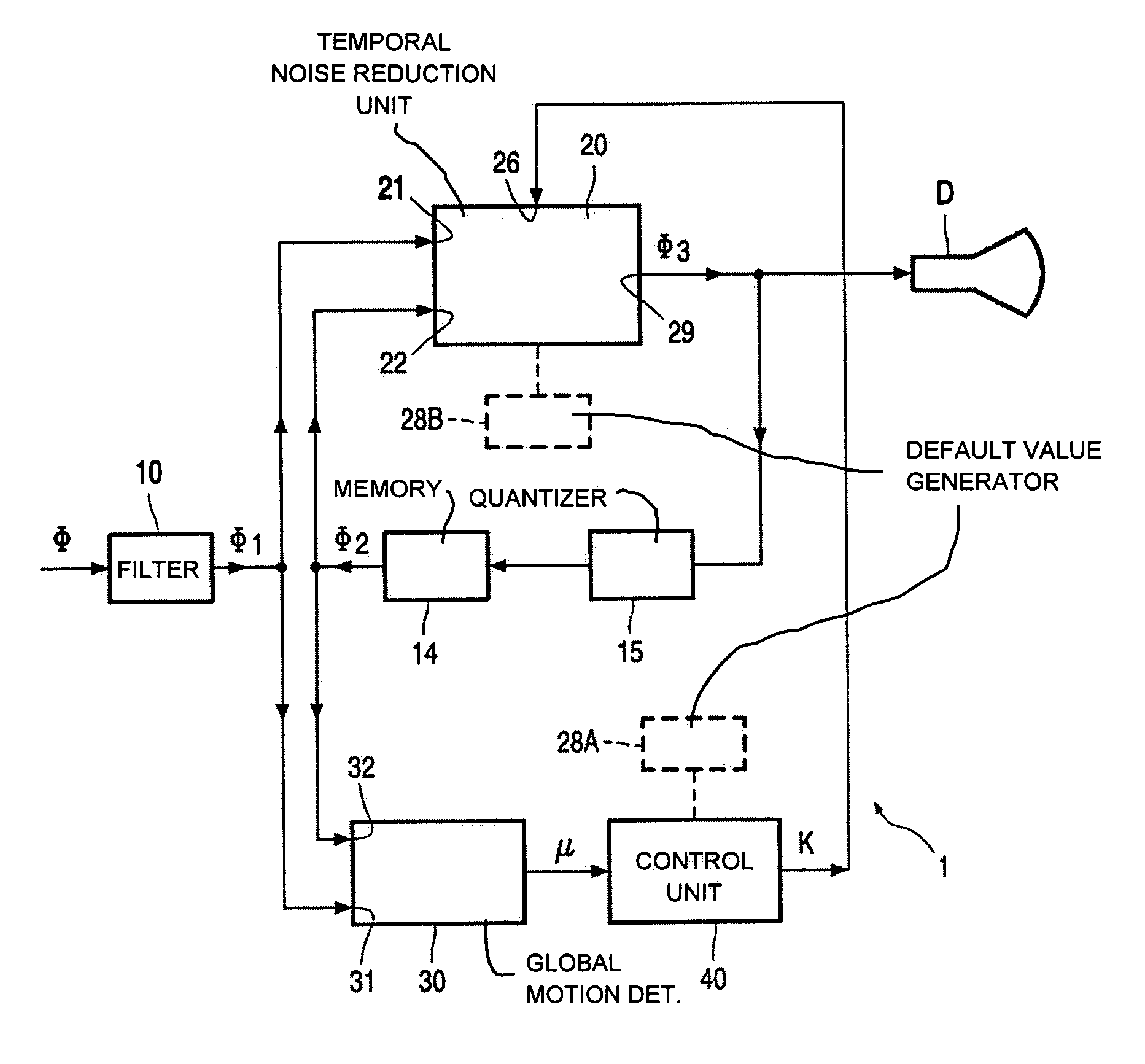
[0018]FIG. 1 schematically shows a block diagram of a filter device 1 in accordance with the present invention. Basically, the filter device 1 comprises a global motion detector 30 and a controllable noise reduction unit 20, and a control unit 40 for controlling the controllable noise reduction unit 20 on the basis of an amount of motion as detected by the global motion detector 30.

[0019]Generally, the global motion detector 30 and the controllable noise reduction unit 20 receive a video signal Φ1. The controllable noise reduction unit 20 operates on its input signal Φ1 to generate an output signal Φ3 with reduced noise. The global motion detector 30 detects the amount of motion in the input signal Φ1. Based on this amount of motion, the control unit 40 adapts the operation of the controllable noise reduction unit 20. Although the control unit 40 might be implemented in hardware, it is preferred for the control unit 40 to be implemented in software.

[0020]The present invention is alr...


PUM


Abstract

A filter device (1) includes a main filter unit (10), such as a 2-D comb filter, implemented in hardware, with an input for receiving a video signal (Φ) and an output for providing a filtered video signal (Φ1), a controllable temporal noise reduction unit (20) receiving the filtered video signal (Φ1) from the main filter unit (10), to perform a noise reduction operation on the filtered video signal (Φ1), and a unit (14, 30, 40) for detecting a very low amount of motion in a video image of the filtered video signal (Φ1) and for controlling the controllable temporal noise reduction unit (20) on the basis of the detected very low amount of motion, so as to enable the filter device (1) to reduce cross-luminance and/or cross-color as well when only a very low amount of motion is present in the signal.

Description

BACKGROUND OF THE INVENTION[0001]1. Field of the Invention[0002]The present invention relates, in general, to the art of filtering of a video signal in order to eliminate cross-effects.[0003]2. Description of the Related Art[0004]As is commonly known, a composite video signal comprises color information and luminance information. When a video signal is received by, for instance, a color television tuner, the luminance signal (Y) and the chrominance signals (U, V) need to be separated. For instance, in a PAL video signal, the video signal has a bandwidth of approximately 5 MHz, wherein the carrier of the color signal is located at about 4.43 MHz. In order to obtain the luminance signal Y, a band suppression filter is needed which suppresses the color carrier. On the other hand, in order to obtain the color signals U, V, a band-pass filter is needed which passes the color carrier and suppresses all other frequencies.[0005]In practice, a 100% separation between the luminance signal Y a...

Claims


Application Information

Patent Timeline
Patent Type & Authority Patents(United States)
IPC IPC(8): H04N5/21H04N9/78H04N9/64
CPCH04N9/646H04N5/14
Inventor PIEPERS, DIRK
Owner FUNAI ELECTRIC CO LTD
Why Eureka
Try Eureka