Spanning tree loop guard

a guard and tree technology, applied in the field of computer networks, can solve the problems of large proliferation of data frames, circuitous paths or “loops” within the network, and high undesirable loops

Active Publication Date: 2006-06-13
CISCO SYSTEMS INC
View PDF19 Cites 91 Cited by
  • Summary
  • Abstract
  • Description
  • Claims
  • Application Information

AI Technical Summary

Problems solved by technology

The existence of redundant links, however, may cause the formation of circuitous paths or “loops” within the network.
Loops are highly undesirable because data frames may traverse the loops indefinitely.
Furthermore, because switches and bridges replicate (i.e., flood) frames whose destination port is unknown or which are directed to broadcast or multicast addresses, the existence of loops may cause a proliferation of data frames so large that the network becomes overwhelmed.
Although the spanning tree protocol provided in the 802.1D standard is able to maintain a loop-free topology despite network changes and failures, re-calculation of the active topology can be a time consuming and processor intensive task.
During this time, message delivery is often delayed as ports transition between states.
Such delays can have serious consequences on time-sensitive traffic flows, such as voice or video traffic streams.
Certain failures associated with such lines can result in the formation of loops that are undetectable by the STP.
Suppose, however, that the trunk link becomes unidirectional.
As described above, the creation of such a loop causes network messages to be replicated, wasting substantial network bandwidth and potentially causing a network outage.
A loop may also be created as a result of an error or failure in the operation of the STP at Bridge B, such as a software error.
Yet, the STP running at Bridge B may fail for some reason to have BPDU messages sent from the port.
Certain hardware failures can similarly result in the creation of loops.
For example, the STP running at Bridge B may generate BPDU messages for transmission from the port coupled to Bride A, but those BPDU messages may never get sent due to a hardware problem at Bridge B.
In summary, unidirectional failures resulting in the formation of loops may occur as a result of malfunctioning or faulty network interface cards (NICs) and / or transceivers, a switch's central processing unit (CPU) being too busy with other processes to send BPDU messages for a relatively long time, a software bug in the STP running at the switch, or congestion algorithms that end up dropping BPDU messages.
In addition, if a link up / down detection and / or autonegotiation protocol is disabled, e.g., by network administrator action, unidirectional failures may go undetected, resulting in loops.

Method used


Image

  • Spanning tree loop guard
  • Spanning tree loop guard
  • Spanning tree loop guard

Examples


Embodiment Construction

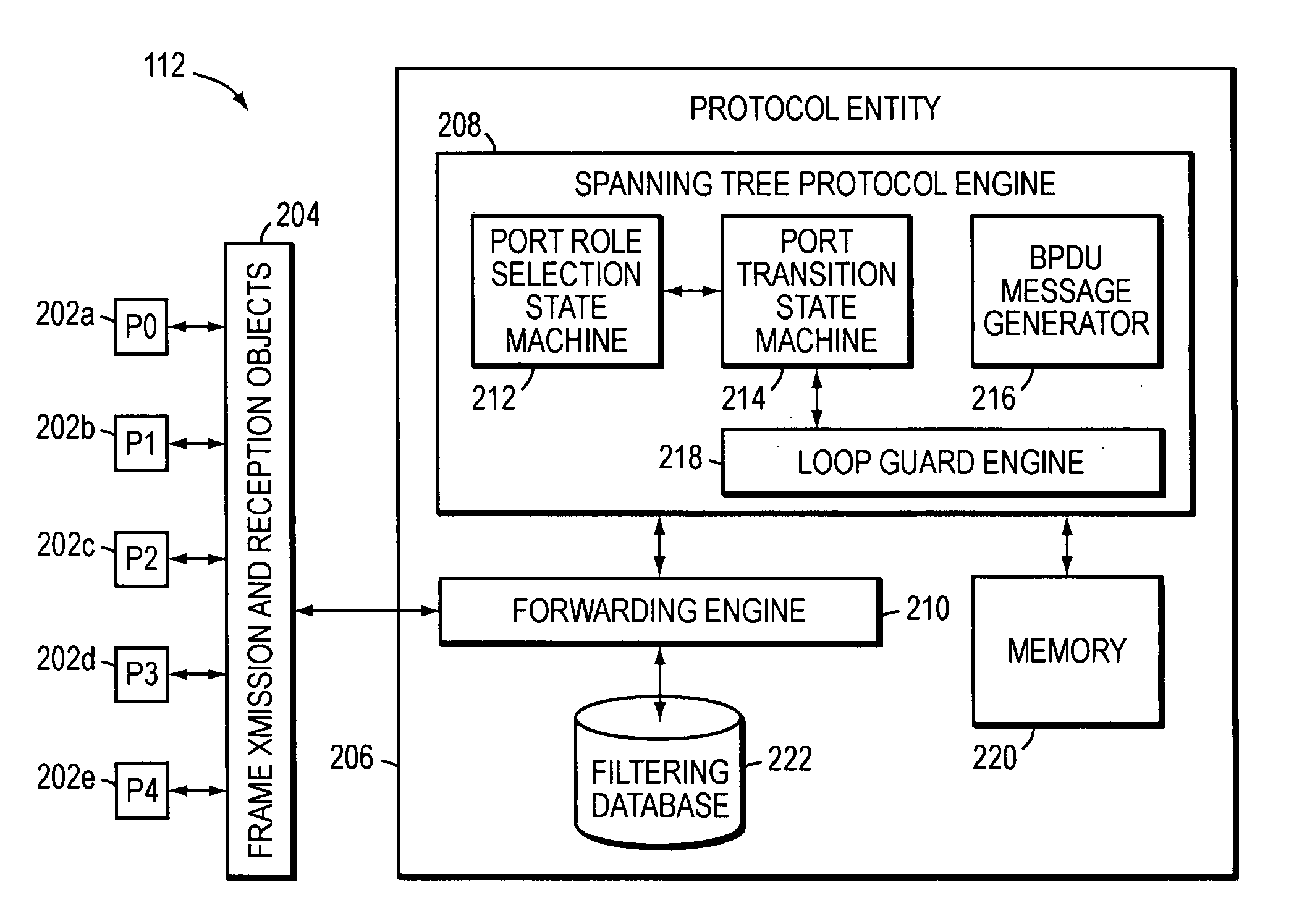
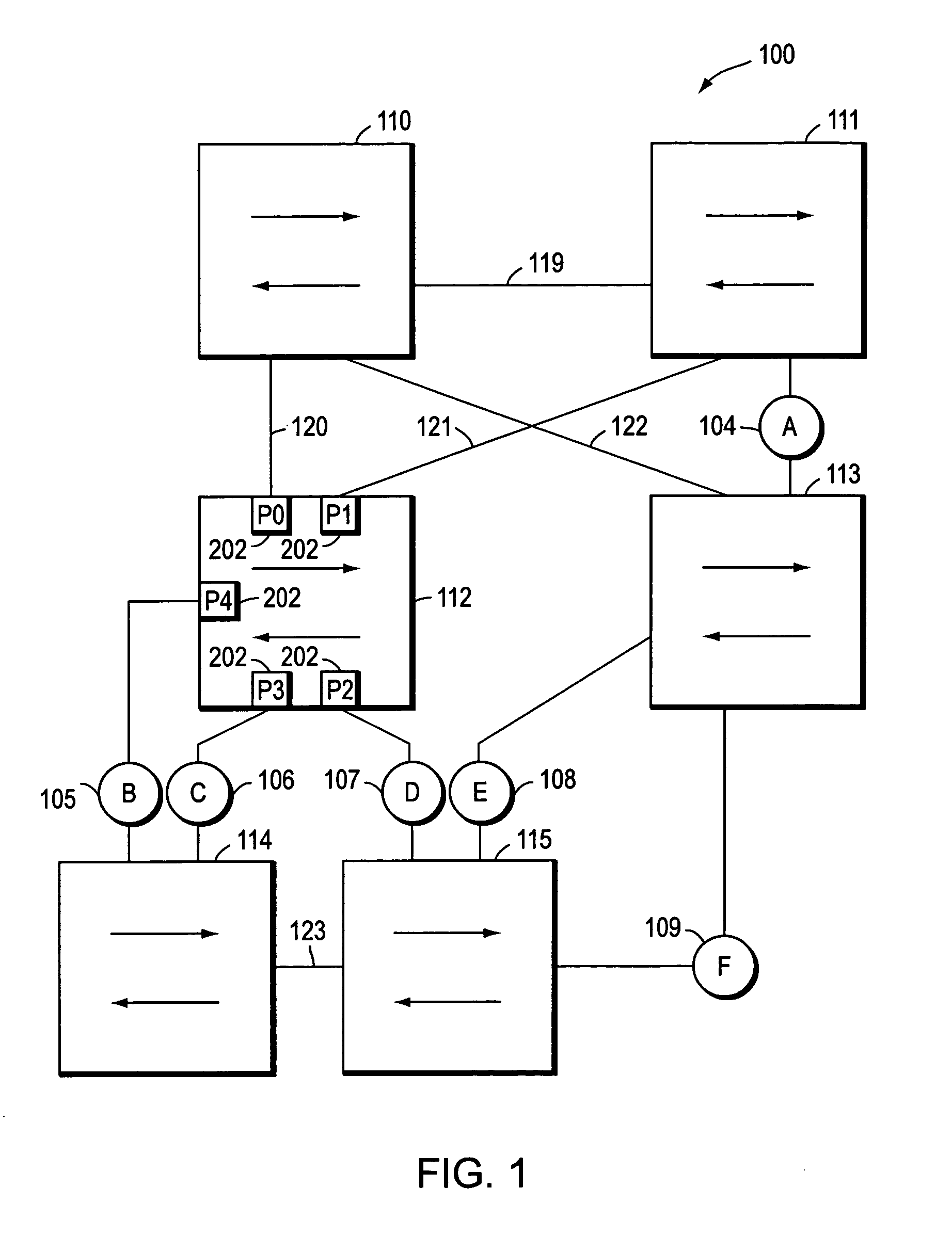
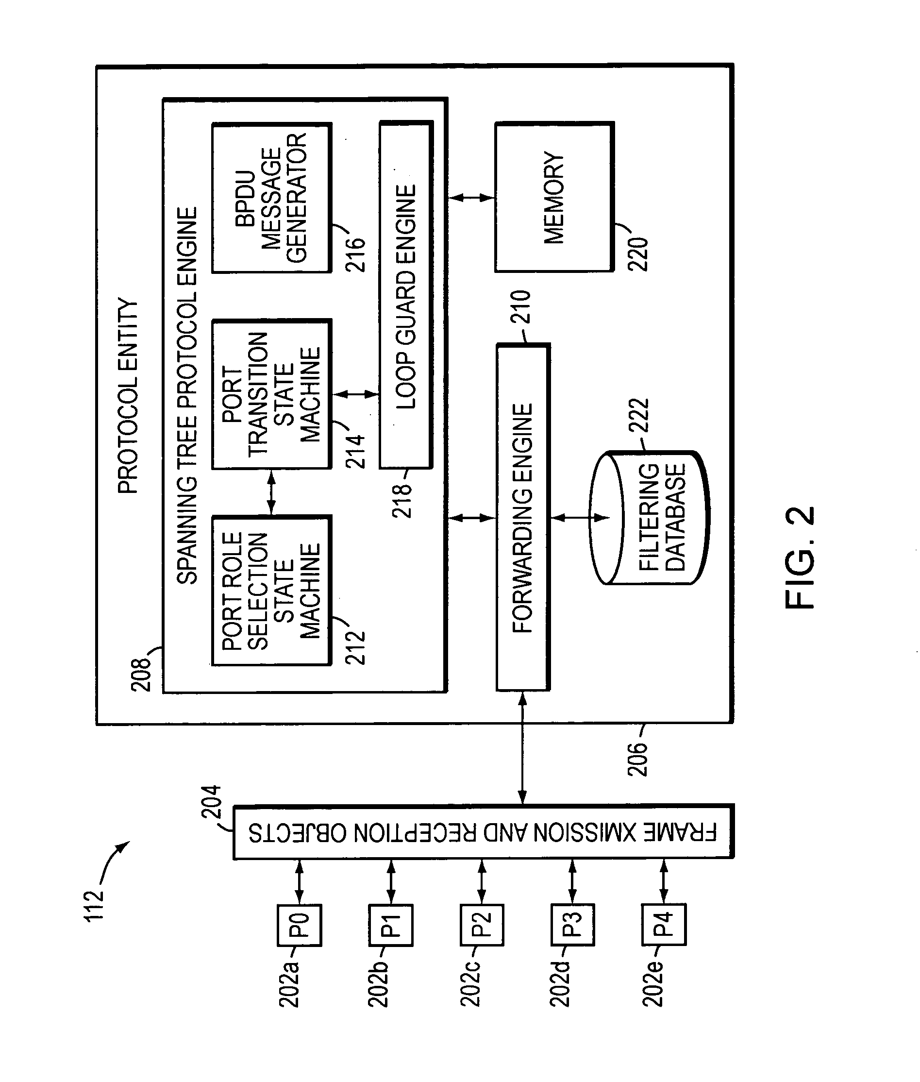
[0028]FIG. 1 illustrates a partially meshed, bridged network 100 in accordance with the present invention. The network 100 preferably comprises a plurality of local area networks (LANs) 104–109 that are interconnected by a plurality of intermediate devices, such as switches 110–115. One or more entities or hosts (not shown) are preferably coupled to each LAN 104–109 so that the entities may source or sink data frames to one another over the network 100. Each switch 110–115, moreover, preferably includes a plurality of ports 202 such that each LAN 104–109 is coupled to at least one port of switches 110–115.

[0029]At least some of the switches 110–115 may be interconnected by a series of links, such as point-to-point duplex links 119–123. Links 119–123 similarly carry messages, such as data frames, between respective switches. Each switch 110–115, moreover, preferably identifies its own ports 202, e.g., by port numbers, such as zero, one, two, three, etc. Switches 110–115 are thus able...


PUM


Abstract

A system and method prevents the formation of loops that are not detected by the Spanning Tree Protocol (STP). An intermediate network device preferably includes a plurality of ports for receiving and forwarding network messages and a STP engine in communicating relationship with the ports. The STP engine transitions the ports among a plurality of spanning tree port states, including a discarding state, a learning state and a forwarding state. The device further includes a loop guard engine that is in communicating relationship with the STP engine and the ports. The loop guard engine monitors the receipt of configuration bridge protocol data unit (BPDU) messages by the ports. If a given port stops receiving BPDU messages, the loop guard engine prevents the STP engine from transitioning the given port to the forwarding state. Instead, the loop guard engine preferably causes the port to transition to a new state in which networks messages are explicitly blocked from being forwarded or received. If the given port subsequently receives a BPDU message, the loop guard engine releases the port from the new state, thereby allowing it to transition to some other spanning tree port state.

Description

BACKGROUND OF THE INVENTION[0001]1. Field of the Invention[0002]The present invention relates generally to computer networks, and more specifically, to a method and apparatus for preventing the formation of loops.[0003]2. Background Information[0004]A computer network typically comprises a plurality of interconnected entities. An entity may consist of any device, such as a computer or end station, that “sources” (i.e., transmits) or “sinks” (i.e., receives) data frames. A common type of computer network is a local area network (“LAN”) which typically refers to a privately owned network within a single building or campus. LANs typically employ a data communication protocol (LAN standard), such as Ethernet, FDDI or token ring, that defines the functions performed by the data link and physical layers of a communications architecture (i.e., a protocol stack). In many instances, several LANs may be interconnected by point-to-point is links, microwave transceivers, satellite hook-ups, etc...

Claims


Application Information

Patent Timeline
Patent Type & Authority Patents(United States)
IPC IPC(8): H04L12/56G06F15/16H04J3/24H04L12/28
CPCH04L12/462H04L45/48H04L45/18H04L45/00
Inventor PORTOLANI, MAURIZIOKALUVE, SHYAMASUNDAR S.FOSCHIANO, MARCO E.
Owner CISCO SYSTEMS INC
Why Eureka
Try Eureka