
Image forming device with image density control

a technology of image density and forming device, which is applied in the direction of instruments, electrographic process equipment, optics, etc., can solve the problems of inability to keep the image density constant, further deterioration of the property of the developing agent, etc., and achieve the effect of stable image density control

Inactive Publication Date: 2006-06-13
RICOH PRINTING SYST
View PDF9 Cites 4 Cited by
  • Summary
  • Abstract
  • Description
  • Claims
  • Application Information

AI Technical Summary

Benefits of technology

[0008]An object of the present invention is to provide an image forming device which performs a stable image density control when a problem is caused during processing of a predetermined number of printing pages, in particular, even when a deterioration of the image due to an abnormal property change of a developing agent is caused.

Problems solved by technology

However, in the conventional toner density control, there is a problem in that, when deterioration of the image density of a patch image is caused due to an abnormal property change of the developing agent, and the deterioration is countermeasured by modifying the developing conditions, such as the toner density and bias voltage, the property of the developing agent is further deteriorated and the image density of the record image can not be kept constant.

Method used


Image

  • Image forming device with image density control
  • Image forming device with image density control

Examples


Embodiment Construction

[0011]Hereinbelow an embodiment of the present invention will be explained with reference to the figure.

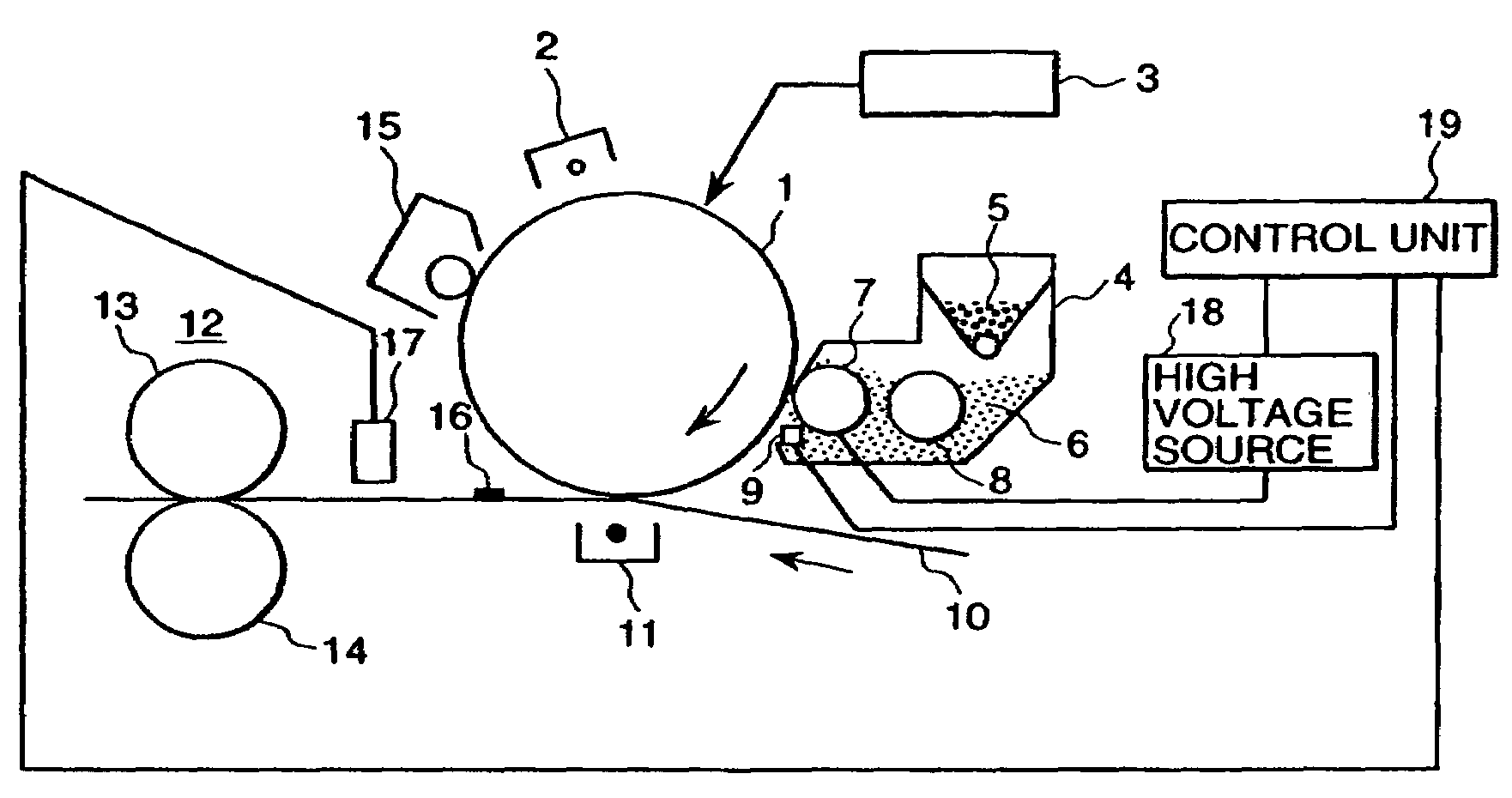
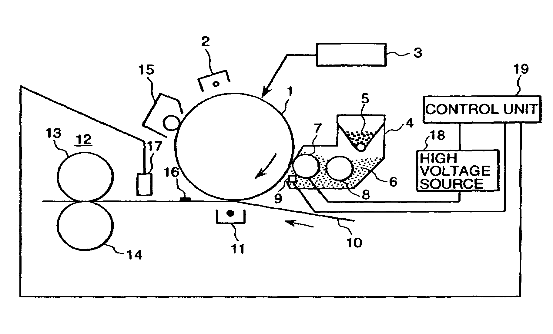
[0012]The figure is a view schematically showing a cross-section of an electrostatic recording device representing the present invention. With reference to this drawing, processes performed by the present device will be explained.

[0013]A photosensitive body 1 having photoconductivity is uniformly charged by an electro-static charger 2, and then a latent image is formed through use of laser beams emitted from an optical device 3. Thereafter, a developing unit 4, which is disposed near and faces the photosensitive body 1, develops the latent image by using a developing agent composed of toners 5 and carriers. This development is performed by transporting the developing agent 6 from a transporting roll 8 to a developing roll 7, by applying a bias voltage having the same polarity as the charge polarity of the toner 5 between the photosensitive body 1 and the developing roll 7, and by ...


PUM


Abstract

An image forming device having a developing unit for visualizing an electrostatic latent image formed on an image carrying body by utilizing a developing agent containing toners and carriers which transfers a toner image to a recording medium to obtain a record image. A patch sensor is provided for detecting the image density of the record image, and it controls toner density stabilization control and an adjustment value and bias voltage in the developing unit according to a value detected by the patch sensor and a value of current flowing in the image carrying body from the developing unit. Thereby, an image forming device is provided which performs stable image density control when a problem is caused during processing of a predetermined number of printing pages, even when a deterioration of the image due to an abnormal property change of a developing agent is caused.

Description

BACKGROUND OF THE INVENTION[0001]The present invention relates to an image forming device which utilizes, for example, an electro photographic method and electrostatic recording method to repeatedly form a large number of images; and, more specifically, the present invention relates to an image forming device that has a control unit which performs adjustment of the toner density and bias voltage in a developing unit according to a value detected by a patch sensor representing the image density of a recorded image and a value of current flowing in an image carrying body from the developing unit.[0002]In a conventional recording device using an electro photographic method, a photoconductive photo-sensitive body is uniformly charged, an image is exposed thereon, a partial discharge of electric charges is produced caused on the photosensitive body and an electrostatic latent image is formed thereon. Thereafter, the electrostatic latent image is developed with toners containing coloring ...

Claims


Application Information

Patent Timeline
Patent Type & Authority Patents(United States)
IPC IPC(8): G03G15/00G03G15/06G03G15/08
CPCG03G15/5062G03G2215/0607G03G2215/00067
Inventor SUZUKI, KATSUHIKO
Owner RICOH PRINTING SYST
Learn More