Computer resource allocating method

Inactive Publication Date: 2006-06-13
HITACHI LTD
View PDF5 Cites 201 Cited by
  • Summary
  • Abstract
  • Description
  • Claims
  • Application Information

AI Technical Summary

Benefits of technology

[0010]An object of the present invention is to provide a method for holding user's security and reducing the load of the managers of a data center and a user even when a network is changed dynamically. Another object of the present invention is to provide a method for changing

Problems solved by technology

In particular, when undertaking company home page management, it is difficult to predict a load due to access from an indefinite number of consumers via the Internet.
Since the data center supplies different computer resources to many user companies, a great number of computer resources must be managed, resulting in increased managing cost.
There are many forms to make a compensating agreement at an unsatisfied guarantee level.
In a method for manually configuring a lo

Method used


Image

  • Computer resource allocating method
  • Computer resource allocating method
  • Computer resource allocating method

Examples


Example

[1] First Embodiment

[0046]First, main drawings necessary to describe the embodiment will be explained.

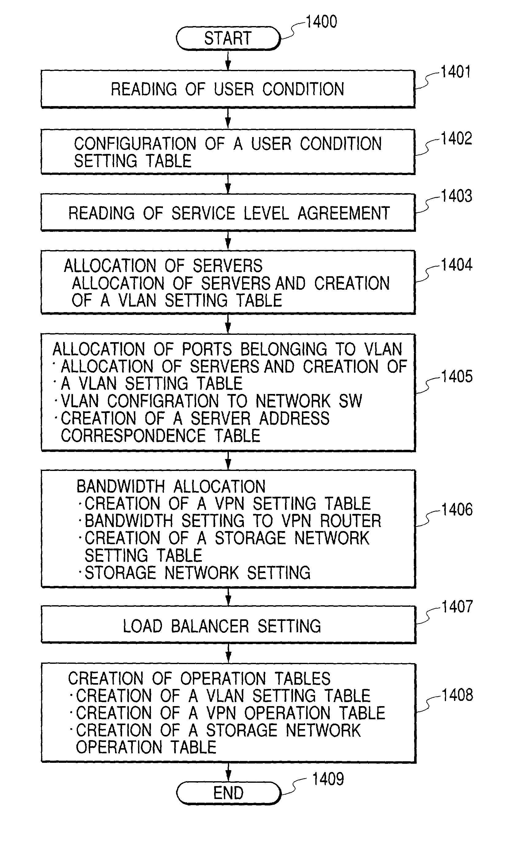
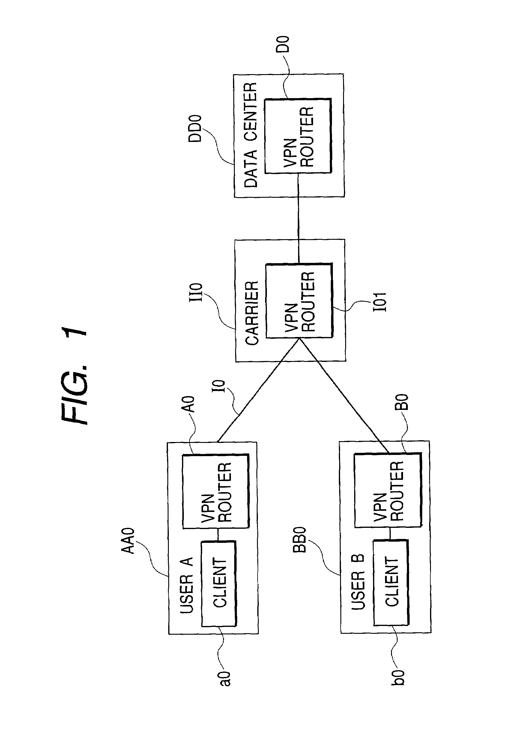
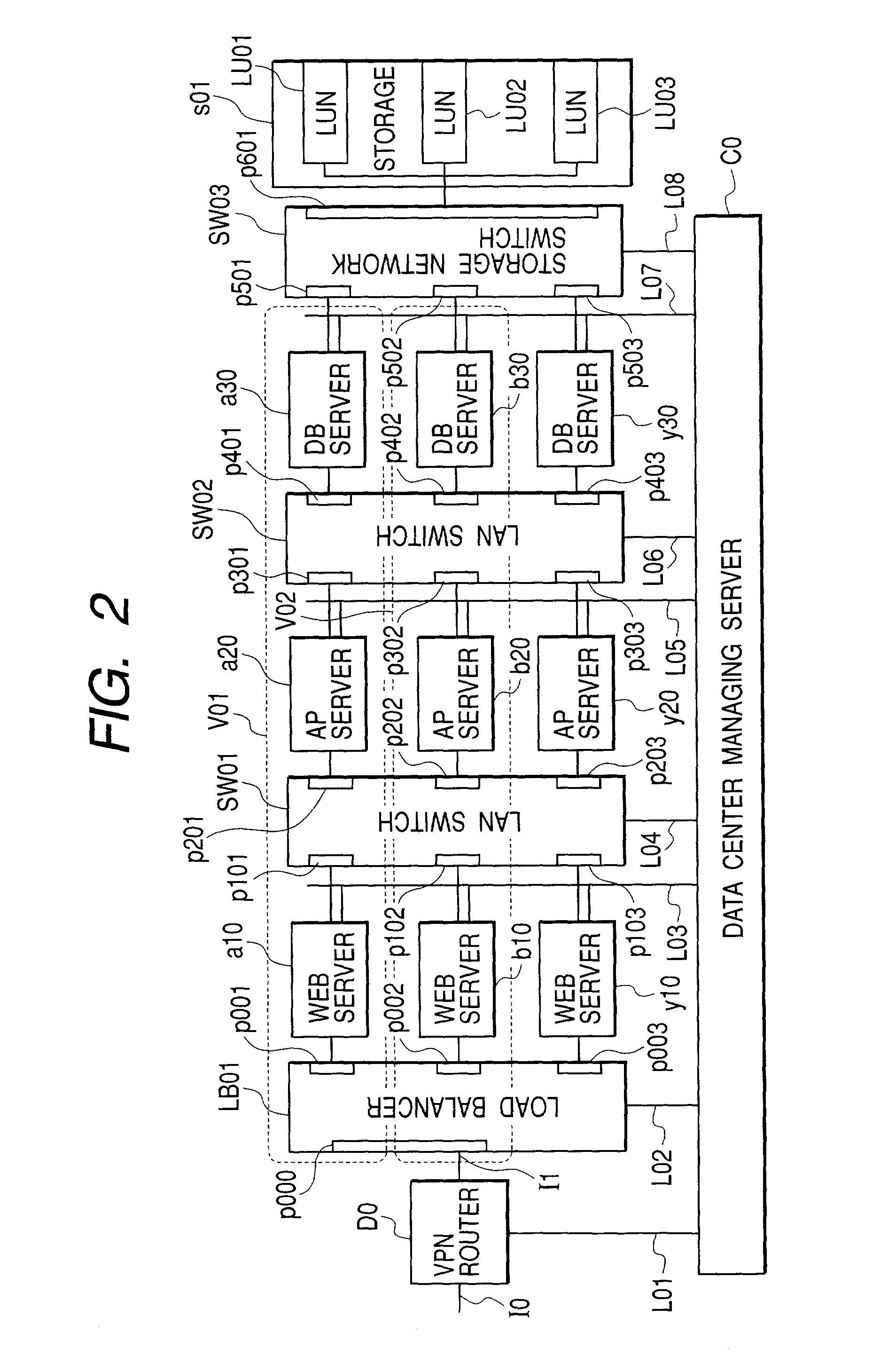
[0047]FIG. 1 shows an example in which a data center targeted in the present invention is connected to a user company A (AA0) and a user company B (BB0) via an Internet line company (carrier) (II0). FIG. 2 shows the internal configuration of a data center DD0 of FIG. 1. User-dedicated VLANS V01 and V02 are configured for each of the users A and B. FIGS. 3 and 4 respectively show VPN configurations from the user to the data center in this embodiment. FIG. 5 shows a main configuration of a storage network. User-dedicated zones Z01 and Z02 are configured for each of the users A and B. FIG. 6 is a diagram to collect server allocation and VLAN-related information possessed by a managing server C0 of the data center DD0. FIG. 7 is a diagram to collect VPN-related information possessed by the managing server C0 of the data center DD0. FIGS. 8 and 9 are diagrams to collect VPN-related infor...

Example

[2] Second Embodiment

[0114]An embodiment in which a data center is configured using a high multiplex SMP server equipped with a partition function virtual computer function PRMF will be described.

[0115]First, main drawings for describing the embodiment will be explained. FIG. 17 shows the internal configuration of a data center in the case of using an LPAR server. FIGS. 18 and 19 show one example of an input screen when the user company A makes a use agreement with this data center. FIG. 20 shows a list of VLAN-related information possessed by the managing server. FIG. 21 shows a list of VPN-related information possessed by the managing server. FIG. 22 shows a list of storage network-related information possessed by the managing server. FIG. 23 shows a list of packets used in the embodiment. FIG. 24 shows a procedure for allocating the CPU utilization of the server to the user who makes the agreement. FIG. 25 shows a procedure to dynamically increase and decrease the CPU utilization...


PUM


Abstract

When a load of a user is fluctuated, a data center dynamically changes resource allocation to the user according to the load and holds security for each user.
A control program on a data center managing server creates a VLAN configuration table so as to allocate a user-dedicated VLAN including plural network switches for each user company, thereby configuring the ports of a load balancer and network switches allocated to a user to the user-dedicated VLAN. A VPN is configured from the user to the data center, whereby a VLAN tagging technique is used to hold security of the user from the user to the data center. The control program compares a user condition setting table created along the service level agreement for each user with the monitoring result of the computer operating state (the CPU utilization history in a VLAN operation table) to dynamically change the computer allocation and VLAN configuration at unsatisfied agreement. Specifically, the VLAN configuration table and the VLAN operation table are changed to change the VLAN configuration in the load balancer and the network switches (in the case of the Web layer). The control program changes the parameter (the sever allocation history in the VLAN operation table) related to charge information based on that.

Description

FIELD OF THE INVENTION[0001]The present invention relates to a method for dividing and allocating resources in a computer system to each user, and more specifically to a resource allocating method which, when processing a request of plural users in a system having a plurality of computers interconnected by a network, provides in real time a computer resource necessary to maintain an agreement with respect to the service contents previously arranged with each user and holds security between users.BACKGROUND OF THE INVENTION[0002]To reduce cost of an information department, a business form to outsource in-company information system operation and company home page management to an ASP (Application Service Provider) is on the increase. There are many forms in such a manner that the ASP outsources computer resource supply and operating management to a data center operator.[0003]The data center operator prepares a great number of computer resources which are divided to plural user compani...

Claims


Application Information

Patent Timeline
IPC IPC(8): G06F15/16G06F9/50H04L12/70H04L12/24H04L12/28H04L12/46H04L12/803H04L12/811H04L29/06H04L29/08
CPCH04L12/4645H04L29/06H04L41/0816H04L67/1008H04L67/1029H04L67/1002H04L2029/06054H04L67/10015H04L67/1001H04L9/40
Inventor YOSHIMURA, YUTAKATARUI, TOSHIAKIMACIEL, FREDERICO BUCHHOLZSHONAI, TORU
Owner HITACHI LTD
Why Eureka
Try Eureka