Method and apparatus for delay line calibration

a delay line and calibration method technology, applied in the field of electronic devices, can solve the problems of inaccuracy and complicated relationships of delay line functions in test instruments, and achieve the effect of convenient programming implementation

Inactive Publication Date: 2006-06-13
TEKTRONIX INC
View PDF9 Cites 16 Cited by
  • Summary
  • Abstract
  • Description
  • Claims
  • Application Information

AI Technical Summary

Benefits of technology

[0010]Portions of both the device and method may be conveniently implemented in programming on a general purpose computer, or networked computers, and the results may be displayed on an output device connected to any of the general purpose, networked computers, or transmitted to a remote device for output or display. In addition, any c...

Problems solved by technology

These mappings ultimately result in very complicated relationships that are based on assumptions about the behavior of the circuits.
Also, var...

Method used


Image

  • Method and apparatus for delay line calibration
  • Method and apparatus for delay line calibration
  • Method and apparatus for delay line calibration

Examples


Embodiment Construction

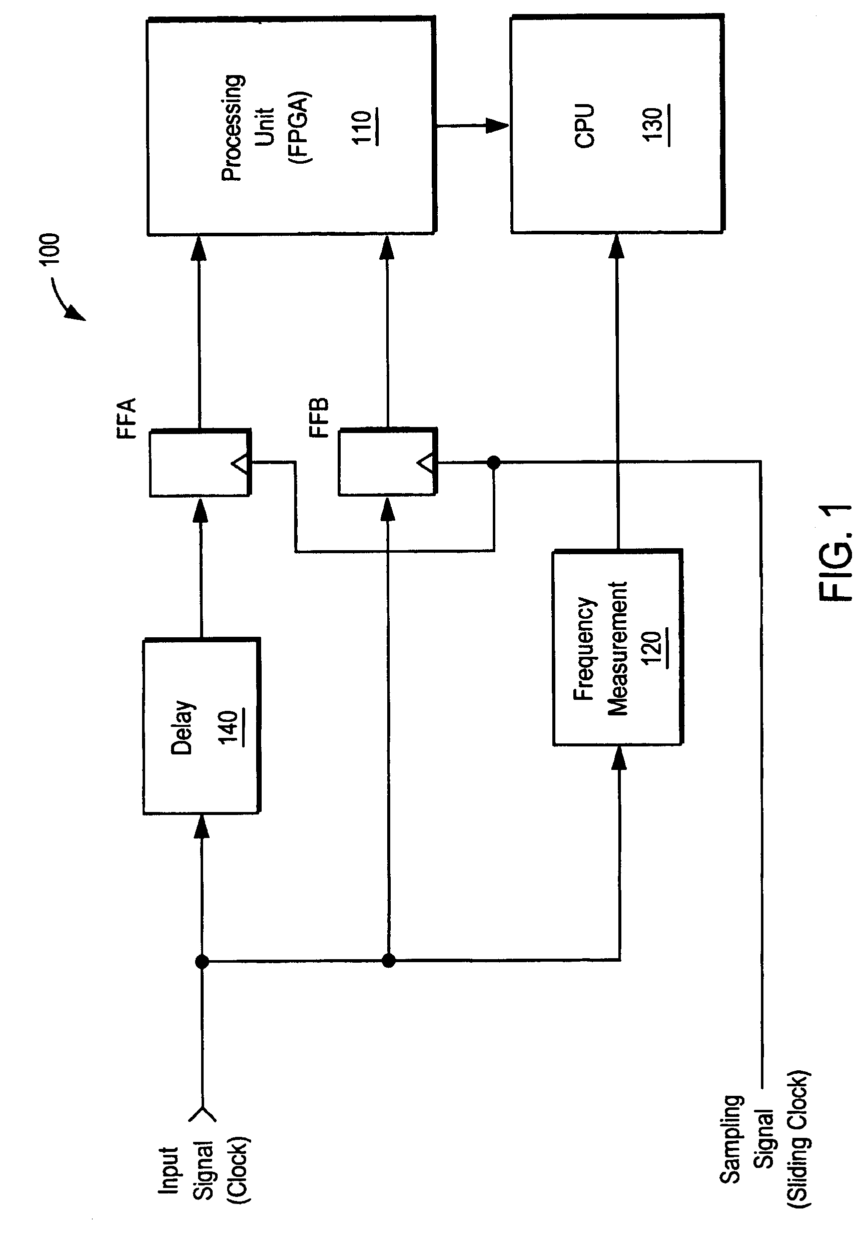
[0020]The present inventors have realized the need to make accurate time delay measurements in a short period of time, and to use measurements as an integral part of electronic instrument calibration. It allows for integral electronic instrument calibration, calibration can be performed during normal use of the test instrument, and the effects of temperature, component aging, sensitivity to operational frequency, power changes, and other effects, can all be accounted for, producing a substantially more accurate instrument.

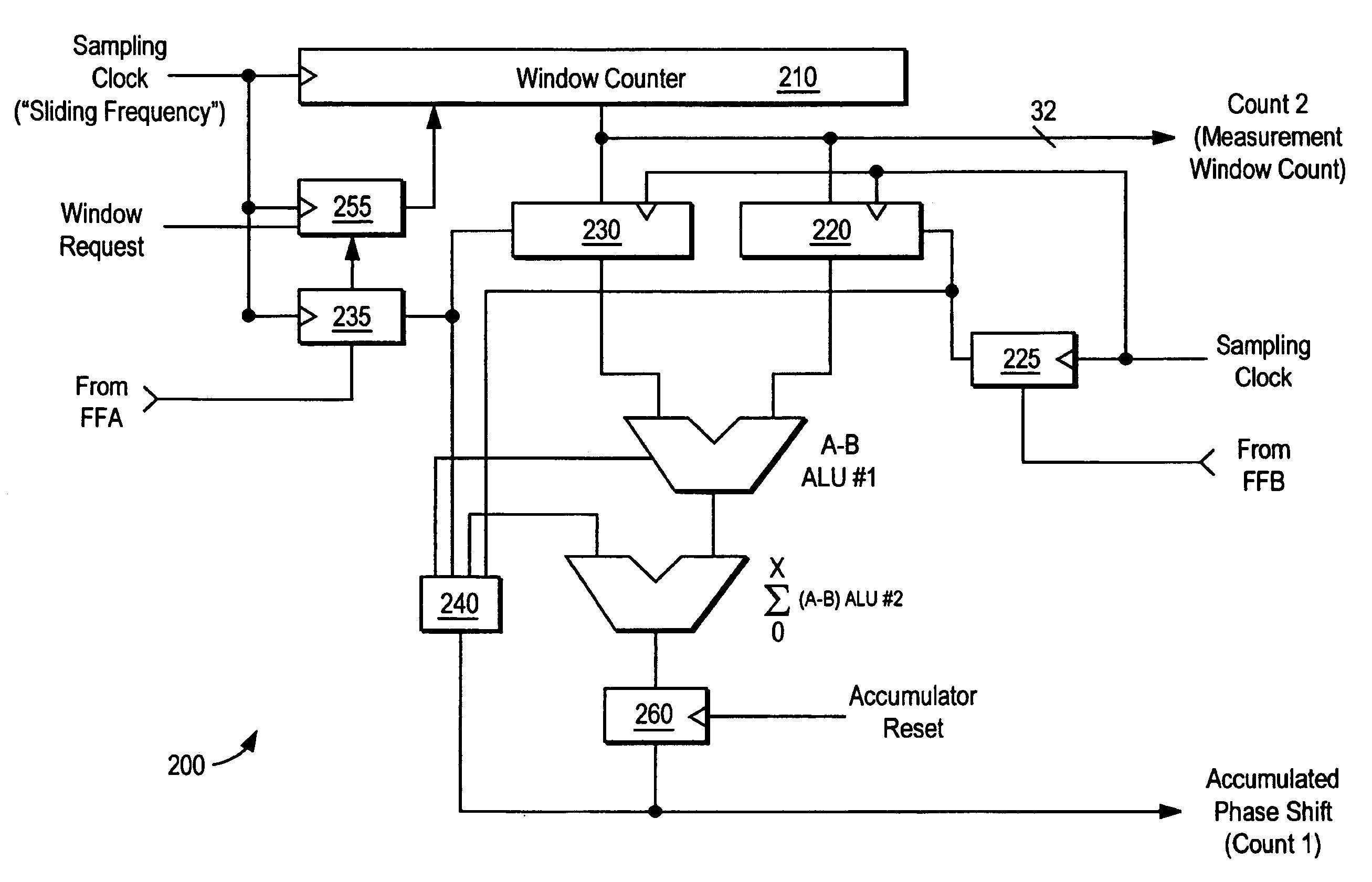
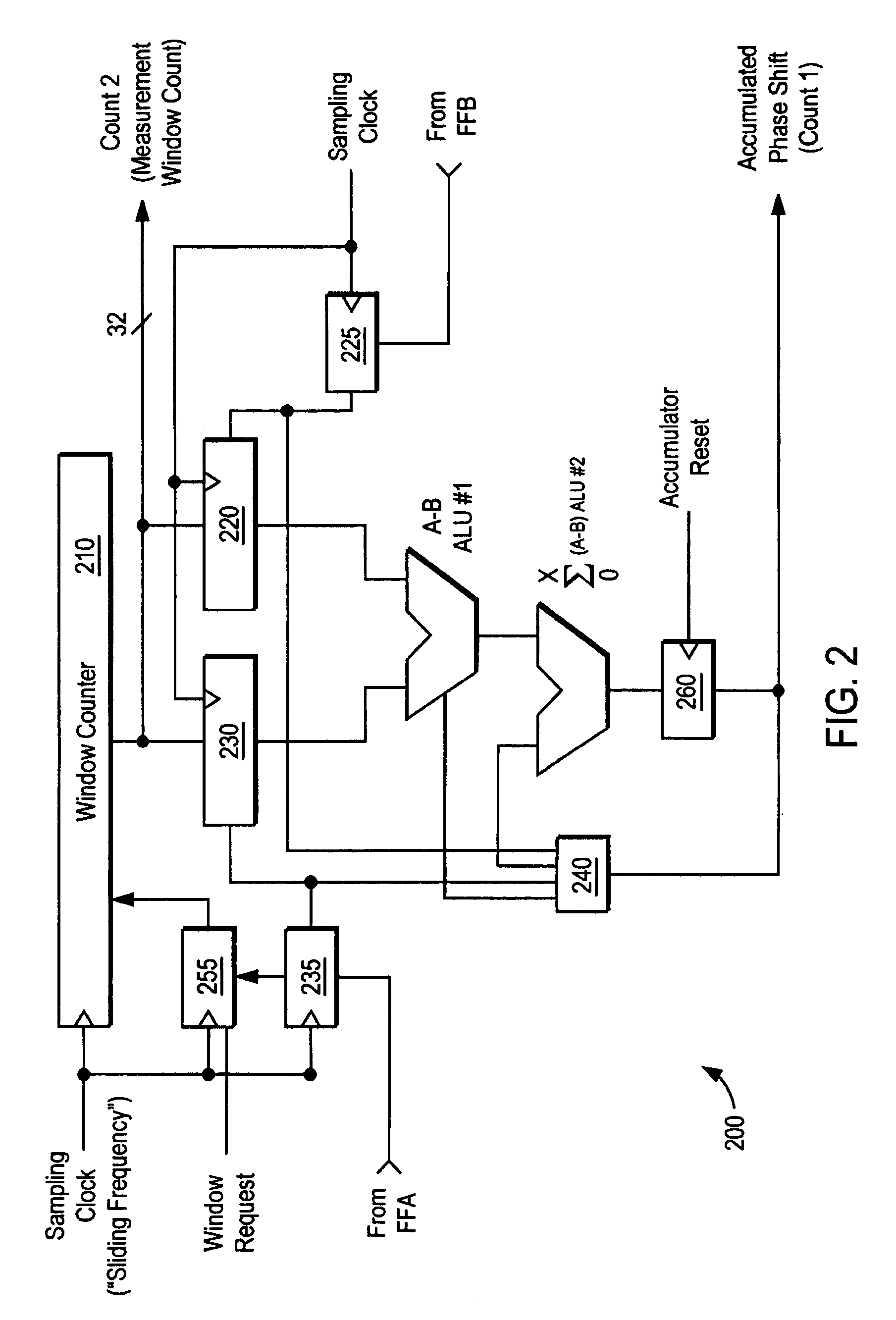
[0021]The present invention utilizes sub-sampling or undersampling of a test signal and a delayed signal, and the sub-samples from each signal are evaluated to determine phase delay between the signals. The phase delay is then used to calculate the amount of delay in a delay line causing the delayed signal to be delayed.

[0022]In the ideal case, sub-sampling or undersampling of a carrier signal (e.g. a test signal) loses the carrier frequency information of the sign...


PUM


Abstract

Sub-sampled signals are compared to determine time delay, calibration of delay elements, and other precise time domain measurements, based on properties of aliased signals produced by the sub-sampling. In one embodiment, flip-flops sub-sample an input signal and a delayed signal. A counter measures time delay between edges in the sub-sampled input and sub-sampled delayed signal. The time delay is determined and averaged over a measurement window, and then scaled to determine an amount of delay of the delayed signal. Means to calibrate a delay element inside a measurement device (e.g., Bit Error Ratio Tester), utilizing sub-sampling techniques to achieve precise measurements very quickly and without the need for factory calibration.

Description

COPYRIGHT NOTICE[0001]A portion of the disclosure of this patent document contains material which is subject to copyright protection. The copyright owner has no objection to the facsimile reproduction by anyone of the patent document or the patent disclosure, as it appears in the Patent and Trademark Office patent file or records, but otherwise reserves all copyright rights whatsoever.BACKGROUND OF THE INVENTION[0002]1. Field of Invention[0003]The present invention relates to calibration of electronic devices. The invention is more particularly related to the calibration of delay lines or elements, particularly for use in test equipment or other devices in which precision time domain measurements are performed.[0004]2. Discussion of Background[0005]Typically, test instruments require calibration of delay lines done at the factory. The calibration is a test configuration that would provide stimulus and measure results on an oscilloscope, then a software program would create translati...

Claims


Application Information

Patent Timeline
IPC IPC(8): G06F17/50
CPCG04F10/06G04F10/00
Inventor POSKATCHEEV, ANDREIHELMER, TOMVERITY, ROB
Owner TEKTRONIX INC
Why Eureka
Try Eureka