Dynamic load-distributed computer system using estimated expansion ratios and load-distributing method therefor

a computer system and dynamic load technology, applied in the direction of program control, multi-programming arrangements, instruments, etc., can solve the problems of low reliability, unsuitable cpu utilization rate in a computer system including smp computers, and unsuitable response time, etc., to achieve the effect of improving response characteristics

Inactive Publication Date: 2006-06-13
NEC CORP
View PDF26 Cites 190 Cited by
  • Summary
  • Abstract
  • Description
  • Claims
  • Application Information

AI Technical Summary

Benefits of technology

[0021]It is an object of the present invention to provide a dynamic load-distributed computer system having a plurality of closely-coupled computers each havi

Problems solved by technology

In the above-described first prior art load-distributed computer system, however, since the CPU utilization rate as the first load index is calculated by the past average value which does not reflect the accurate current load, the reliability is not high.
Also, the CPU utilization rate is not appropriate in a computer system including SMP computers.
However, when a message requesting a transaction process arrives, the response time thereof is not obtained at this time, so that the response time is not an appropriate load index.
However, as explained above, the reliability for a dynamic control is not high, and this determination is not appropriate in a SMP computer.
Therefore, when all the computers are overloaded, the load distribution may be not appropriate.
Further, this technology is not intended to decrease the minimum response time for arrival transactions and for the entire system.
In the abo

Method used


Image

  • Dynamic load-distributed computer system using estimated expansion ratios and load-distributing method therefor
  • Dynamic load-distributed computer system using estimated expansion ratios and load-distributing method therefor
  • Dynamic load-distributed computer system using estimated expansion ratios and load-distributing method therefor

Examples


first embodiment

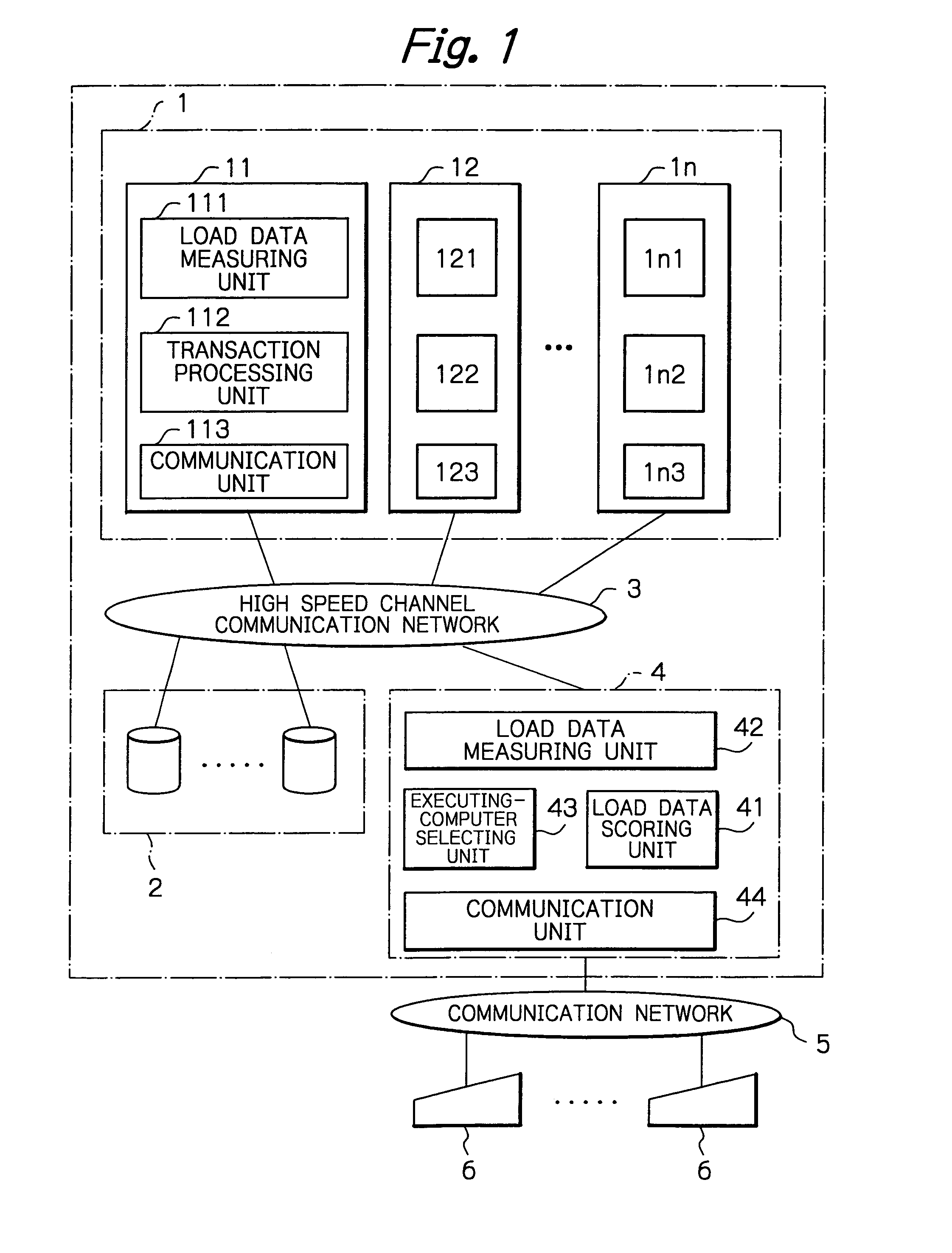
[0048]In FIG. 1, which illustrates the load-distributed computer system according to the present invention, reference numeral 1 designates a computer apparatus formed by a plurality of computers 11, 12, . . . , 1n each including a load data measuring unit 1i1, a transaction processing unit 1i2 and a communication unit 1i3. The computer apparatus 1 is connected to a file apparatus 2 formed by a plurality of disk units through a single high speed channel communication network 3.

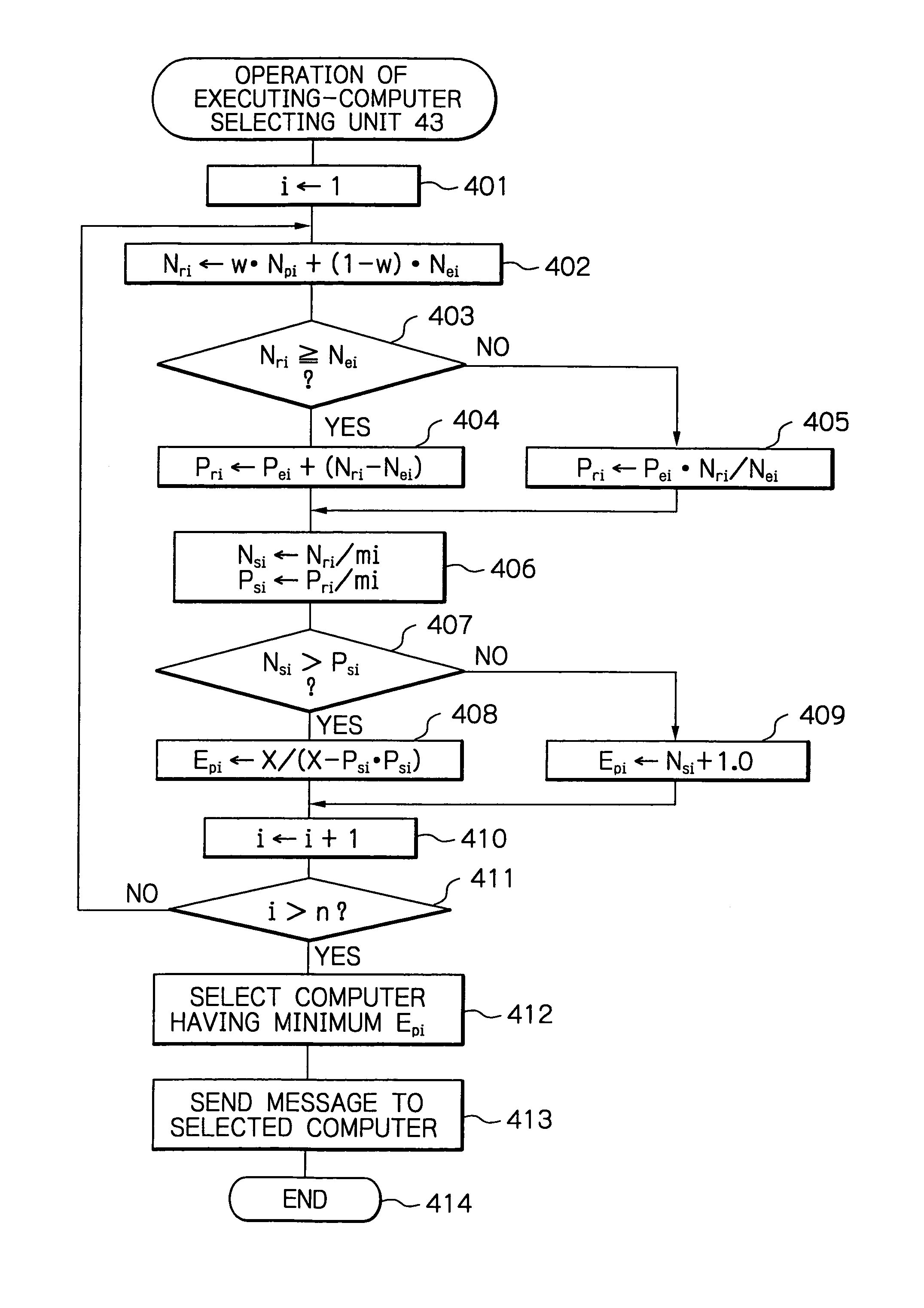
[0049]Also, a relay distributing apparatus 4 is connected via the high speed channel communication network 3 to the computer apparatus 1. The relay distributing apparatus 4 is formed by a load data storing unit 41, a load data measuring unit 42, an executing-computer selecting unit 43 and a communication unit 44.

[0050]The load-distributed computer system of FIG. 1 is connected via a communication network 5 to a large number of external terminal units 6.

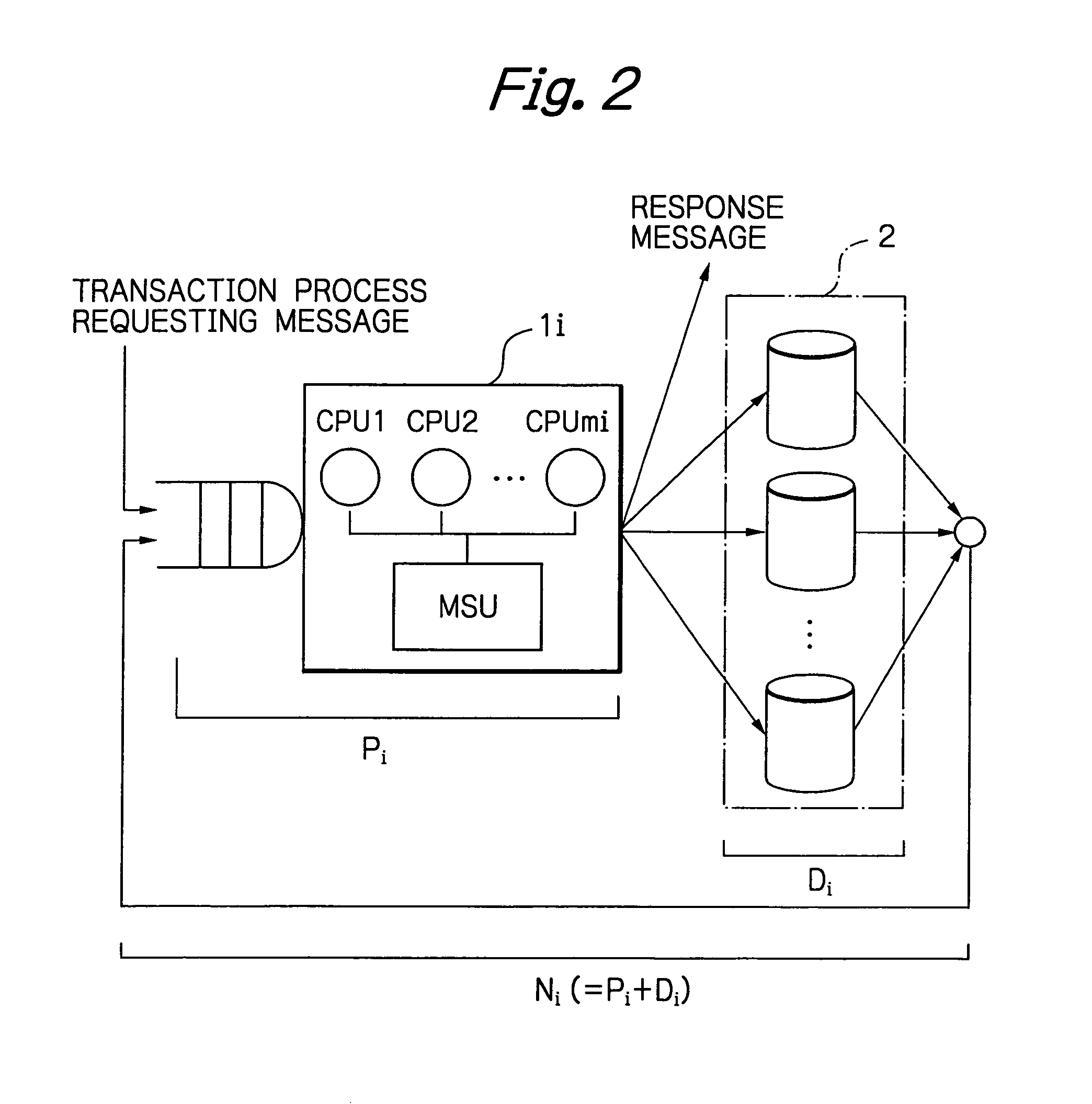
[0051]In FIG. 2, which illustrates one computer 1i of the c...

second embodiment

[0146]In FIG. 10, which illustrates the load-distributed computer system according to the present invention, the relay distributing unit 4 of FIG. 1 is not provided. Instead of this, one load data storing unit 1i4, one load data measuring unit 1i5 and one executing-computer selecting unit 1i6 corresponding to the load data storing unit 41, the load data measuring unit 42 and the executing-computer selecting unit 43, respectively, of FIG. 1 are provided, and an exchange / store unit 10 is connected to the computer 11, 12, . . . , 1n. Note that the hardware of the computer 1i is also illustrated in FIG. 2.

[0147]In the computer system of FIG. 10, in each of the computers 1i, at predetermined time periods, the load data measuring unit 1i1 measures a load data. Then, the load data measuring unit 1i5 changes the load data into an estimated load data and stores it in the load data storing unit 1i1. Simultaneously, the estimated load data is transmitted via the exchange / store unit 10 to the l...

third embodiment

[0173]In FIG. 13, which illustrates the load-distributed computer system according to the present invention, a relay provisional-distributing unit 7 is provided between the computers 11, 12, . . . , 1n and the communication network, 5 of FIG. 10, in order to distribute a message requesting a transaction process among the computer 11, 12, . . . , in statically or quasi-statically in accordance with the following methods in combination or individually.

[0174]1) distribution by dividing the terminal units 6 into a plurality of groups each corresponding to one of the computers 11, 12, . . . , 1n;

[0175]2) distribution by sequentially messages arrived at the relay provisional-distributing unit 7 to the computers 11, 12, . . . , 1n in accordance with the numbers of CPUs therein; and

[0176]3) stochastic distribution in accordance with result data.

[0177]In the distribution 1), each of the terminal units 6 is allocated in advance to one of the computers 11, 12, . . . , 1n. In the second embodi...


PUM


Abstract

In a method for distributing a transaction in a computer system including a plurality of computers each formed by processors, a plurality of estimated loads are calculated for the computers. Then, a plurality of estimated process time expansion ratios are calculated for the computers, in accordance with the estimated loads and the numbers of processors in the computers. Then, a plurality of load indexes one for each of the computers are calculated in accordance with the estimated process time expansion ratios. Finally, the transaction is distributed in accordance with the load indexes.

Description

BACKGROUND OF THE INVENTION[0001]1. Field of the Invention[0002]The present invention relates to a dynamic load-distributed computer system including tightly-coupled computers which is called a cluster structure.[0003]2. Description of the Related Art[0004]In a load-distributed computer system including tightly-coupled computers, each computer formed by a plurality of symmetrical type multi-processors (SMPS), i.e., central processing units (CPUs), when a large number of messages requesting transaction processes arrive at the computer system, the messages are optimally distributed to the computers to enhance the performance of the computer system. Generally, since each transaction process is a small job, after one of the computers is selected to process this transaction process, the transaction process is completely carried out by the selected computer. Also, since transaction processes are generally interactively processed, the target of the load distribution is to minimize the aver...

Claims


Application Information

Patent Timeline
IPC IPC(8): G06F9/46G06F9/50
CPCG06F9/505
Inventor KUBO, HIDEHITOTAKANO, YOSUKE
Owner NEC CORP
Why Eureka
Try Eureka