Straight type riveting gun

a riveting gun and straight-type technology, applied in the direction of metal-working machine components, metal-working tools, metal-working apparatus, etc., can solve the problems of limited riveting operation, uneven riveting operation of the riveting gun in the vertical direction, and inconformity with ergonomics, so as to facilitate the operation and beautify the outward appearance of the machine body, the effect of preventing damag

Inactive Publication Date: 2006-06-20
LIN YU CHING
View PDF8 Cites 9 Cited by
  • Summary
  • Abstract
  • Description
  • Claims
  • Application Information

AI Technical Summary

Benefits of technology

[0006]The main object of the present invention is to provide a straight type riveting gun. By means of its straight design, it may be applied to a location where the operation needs to be performed in vertical direction. Moreover, the straight type riveting gun may be hung by use of the hanging hole that forms on its end so as to help to take it out and facilitate its operation.
[0007]Another object of the present invention is to embed the interactive connecting rod of the straight type riveting gun in the machine body of the riveting gun. A trigger on the outside of the machine body actuates the riveting gun. The hidden connecting rod beautifies the outward appearance of the machine body and prevents from damage caused by unexpected collision.
[0008]The still another object of the present invention is to provide a straight type riveting gun for automatically ejecting a rivet through pneumatic action, which sucks the rivet before operation and ejects the rivet after operation so as to achieve the purposes of rapid operation and easy use.

Problems solved by technology

However, for the riveting gun, which is operated in the vertical direction, the riveting operation is limited by the intersected structure of the riveting device and the handle.
The riveting operation of the riveting gun in vertical direction is not smooth and does not comply with ergonomics.
Accordingly, the pneumatic hydraulic riveting gun is not suitable for the riveting operation in vertical direction.
Because the devices are exposed to the outside, the connecting rod easily gets loose or suffers from damage due to collision.
Besides, the conventional riveting gun lacks the beautiful appearance.
According to this operation method for ejecting the rivet, the operator must change the angle of the riveting gun unceasingly.
Moreover, the required time for free falling of the rivet is very long and further affects the speed of the riveting operation.

Method used


Image

  • Straight type riveting gun
  • Straight type riveting gun
  • Straight type riveting gun

Examples


Embodiment Construction

[0018]In order to achieve the aforementioned objects, the present inventor discloses a straight type riveting gun. The detailed structural feature and the preferred embodiment of the present invention will now be described in detail with reference to the accompanying drawings.

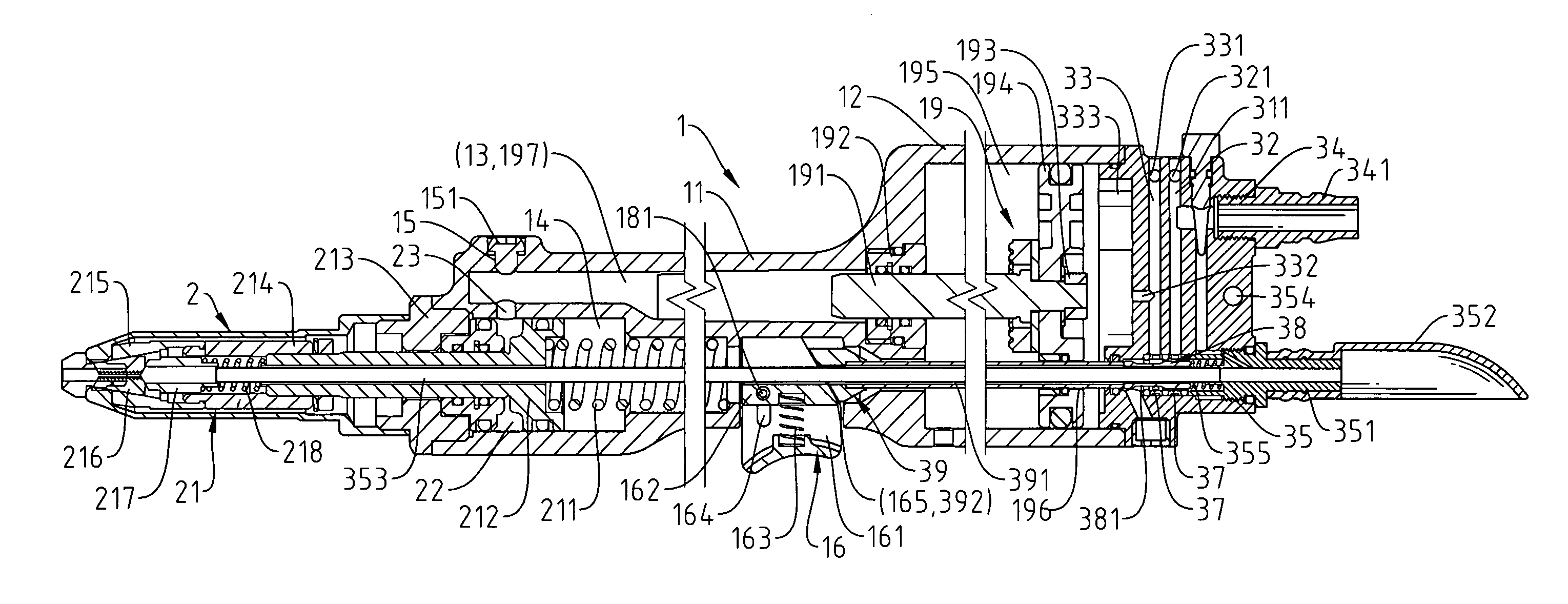
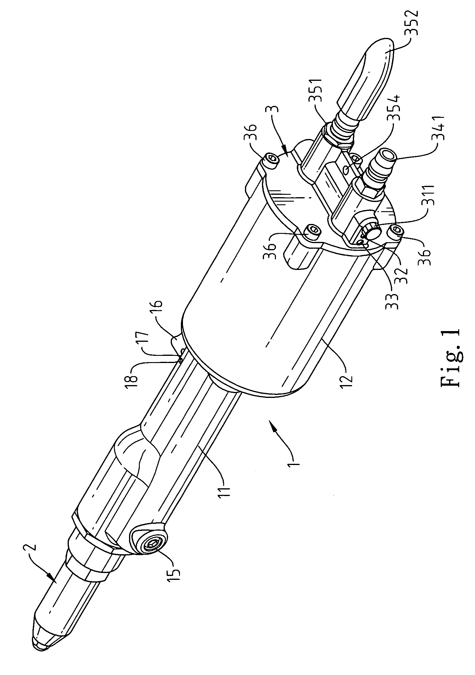
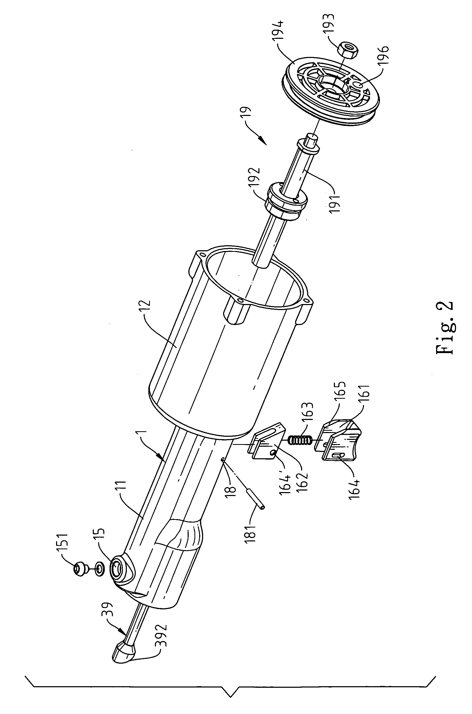
[0019]Referring to FIG. 1 through FIG. 6, the straight type riveting gun of the present invention comprises a gun body 1, a front gun pipe 2, and a back cover 3. The gun body 1 is composed of a pipe body 11 and a tube body 12, wherein the front gun pipe 2 is locked to a front end of the pipe body 11 and locking devices 36 are locked to a tail end of the tube body 12. The inside of the tube body 11 is divided into an upper tunnel 13 and a lower tunnel 14 and communicated with the tube body 12. An oil-filling hole 15 is formed at the front end of the pipe body 11. Moreover, a bolt 151 is utilized to open or close the oil-filling hole 15, and a trigger hole 17 for receiving a trigger 16 is formed at a tail end of ...


PUM

PropertyMeasurementUnit
suction forceaaaaaaaaaa
pressureaaaaaaaaaa
weightaaaaaaaaaa

Abstract

The present invention relates to a straight type riveting gun, which comprises a gun body having a pipe body and a tube body, a front gun pipe, and a back cover, wherein the front gun pipe is locked to front end of the pipe body and the back cover is locked to the tail end of the tube body. The tube body is provided for receiving a rivet-ejecting adaptor of an oil pressure rod. A trigger is mounted at the tail end of the pipe body for pushing a trigger ejector rod. The trigger ejector rod moves a valve to allow the exterior gas to enter a gas-collecting room for forcing a pneumatic piston to perform movement by use of air pressure. The oil pressure rod pushes the oil liquid to allow the riveting rod to generate powerful pulling force instantaneously thereby completing the riveting operation.

Description

FIELD OF THE INVENTION[0001]The present invention relates to a straight type riveting gun, and more particularly to a riveting gun structure, which performs the riveting operation by pneumatic oil pressure, and which triggers the liquid pressure by air pressure to backwardly move the pneumatic piston for performing the riveting operation. By use of the handle and the intake terminal that align the same line, the straight type riveting gun of the present invention may be applied to various working conditions.BACKGROUND OF THE INVENTION[0002]The riveting gun is a specialized manual tool for industry and decoration. In the conventional riveting gun, the handle and the riveting device are intersected with one another. Therefore, it is primarily employed to rivet two parallel boards. However, for the riveting gun, which is operated in the vertical direction, the riveting operation is limited by the intersected structure of the riveting device and the handle. The riveting operation of the...

Claims


Application Information

Patent Timeline
Patent Type & Authority Patents(United States)
IPC IPC(8): B23Q15/00B21J15/28
CPCB21J15/043B21J15/105B21J15/22Y10T29/53065Y10T29/53748
Inventor LIN, YU-CHING
Owner LIN YU CHING
Why Eureka
Try Eureka